Brentmail.gif (2788 bytes)
div.GIF (2822 bytes)
Main
div.GIF (2822 bytes)
F-Bodies
1994 Supercharged
Z28 Camaro

-
1996 450hp n/a
Z28 Camaro SS

-
1995 Trans Am
-
4th Gen Appearance
Modification Guide

F-Body Install & Fix-it Guides
My Previous F-Bodies
My Favorite F-Body
Links

div.GIF (2822 bytes)
1995 Ninja ZX6
1991 KX250
div.GIF (2822 bytes)
Other Hobbies
div.GIF (2822 bytes)
About Me
div.GIF (2822 bytes)

Special Thanks to
LV-F-Body Association &
Badassride.com

for hosting this site!


so.GIF (3628 bytes)

sr.GIF (4207 bytes)

sa.GIF (3935 bytes)

sm.GIF (3802 bytes)

sa.GIF (3935 bytes)

sc.GIF (3799 bytes)

Brent Franker's
4th Generation Alarm Installation Guide

for the 1996 to 1998 F-Body

flazbar.gif (4688 bytes)

To start with, I'll give you a quick rundown of the common wires and locations that are used in most alarm installs.

These locations will go for both the Camaro and Firebird/Trans Am.   However, since I did the install pictured below on a 1996 Camaro SS, you Firebird/Trans Am guys will have to improvise just a little when viewing the pictures below :)  The following table will give you OPTIONS for where to splice into the particular wire.  In one case, the book may suggest using a certain wire and maybe I didn't like this one so I used a different wire :)  If I did this, I'll let you know but I'll also give you what my install book lists.  Remember, there are about a 1000 different ways to install an alarm and this is just one variation :)

Purpose Wire Color Location and Notes
Constant 12 volts RED or Ignition switch harness
  ORANGE Back of fuse block... see pics below. 
Ignition 12 volts PINK or Ignition switch harness
  YELLOW Back of fuse block... see pics below. 
Starter YELLOW or Ignition switch harness
  PURPLE At theft deterrent relay... see pics below.
Dome lights WHITE ( - ) At Body Control Module.  NOTE:  The Body Control Module (BCM) is located behind the passenger dash below the glove box.   WHITE ( - ) wire at BCM covers both front doors and trunk.  Optional door trigger, GRAY/BLACK ( - ) covers driver door and BLACK/WHITE   ( - ) covers passenger door at 32 pin Blue connector at BCM.  Diode isolation needed:  band side of diode faces OEM wires.
Trunk pin switch ORANGE/BLACK   ( - ) At Body Control Module.
Parking lamps BROWN ( + ) At headlight switch.  Easy access if fuse block removed... see pics below.
Power lock RED/BLACK At Body Control Module... see details below... complicated :-)
Power unlock ORANGE/BLACK & GRAY/BLACK Again, at Body Control Module... see details.
Window Up Driver DARK BLUE At main switch... see details below.
Window Down Dr. BROWN At main switch
Window Up Pass. LIGHT BLUE At main switch
Window Down Ps. TAN At main switch
Trunk Release BLACK/WHITE (+) At hatch release relay.  Again, this is a bit complicated so see details below :)
OEM Horn BLACK ( - ) Steering column harness
Headlights YELLOW ( + ) At headlight switch.  Easy access if fuse block removed.
Tach Signal WHITE 8 cylinder engine tach wire is white at Powertrain Control Module (PCM) under hood on passenger rear of engine compartment.   6 cylinder engine tach wire is WHITE at ignition control module on driver front of engine.  WHITE tach wire can also be found in the 10 pin Blue connector in passenger kick panel on both the 8 and 6 cylinder.
Ignition #2 ORANGE Ignition switch harness (heat/AC)
Accessory BROWN Ignition switch harness
Neutral Safety ORANGE/BLACK    ( - ) At switch on base of gear select switch.   Wire can also be found in 10 pin blue connector in passenger kick panel.
Brake Light LIGHT BLUE ( + ) At switch above brake pedal
Reverse Light LIGHT GREEN (+) At switch on base of gear select switch.

The above is just to give you an idea of what to look for.  I'll try to go into detail for each wire below.

flazbar.gif (4688 bytes)

First off, let me just say again that there are literally hundreds of different ways, methods, whatever to install an alarm system.   If you don't like the way I do it, then quit reading this page ;-)  I often don't solder connections as I've found the connectors I use to work very well.  Some say you should solder all connections... well, I don't necessarily agree :)  If you want, feel free to solder when ever and where ever you want!  Also, the order in which the install is done isn't set in stone.  You can do it however you wish.   The purpose of this page is to provide guidance... it's not the only way it can me done! :)  Well, lets get started!

flazbar.gif (4688 bytes)

Supplies and Tools

To install an alarm, you're going to need a few basic tools and supplies.

alarm01a.JPG (36397 bytes)

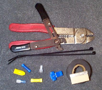
Here are some of the items I can think of that you'll probably end up needing.

Wire stripper and crimper
Electrical tape
Razor blade to cut electrical tape around factory wires
Phillips head screwdriver
Socket set or nut driver set
Blue and Yellow butt connectors
Female spade connectors (maybe... for relay connections)
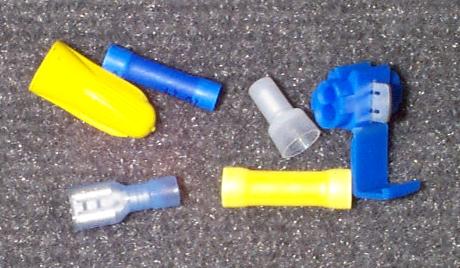
Blue quick splice connectors are a must!
Wire nuts and/or caps
A drill and various drill bits (to mount L.E.D.)
Possibly a soldering iron but maybe not!  See below...
Extra "hook up" wire... can be purchased at Radio Shack

Here is a close-up of the blue quick splice connectors that will make your install MUCH easier!

alarm01b.JPG (30741 bytes)

flazbar.gif (4688 bytes)

Learn Your Alarm

The first thing you want to do is familiarize yourself with your alarm system.  Lay everything out and take the time to read through the instructions and installation manual.  At each point in the installation manual, take a look at the component the manual is talking about and where it plugs into/connects to the alarm.  It is important that you at least read through the manuals once.  This way, things will start "clicking" when we go along :-)

alarm01.JPG (21190 bytes)

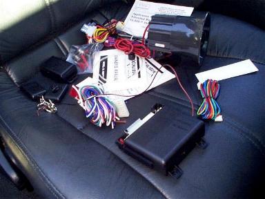
Looking at all this stuff and huge clumps of wires may be a bit intimidating, but don't worry, we'll work through it :-)

flazbar.gif (4688 bytes)

Installation Pages

I got a little carried away making this guide :)   When I went to test it, half the pictures showed up as an "x" image on my computer!  There was far too much information and pictures for one page so I had to break it down into four different sections.  These sections are listed below.  I recommend going through them in order as that is how I laid out the project.  Enjoy!

flazbar.gif (4688 bytes)

I hope you enjoyed this guide and got some use out of it!  I always like to chat with fellow F-Body buds so feel free to send me your comments or suggestions!  My email is

bfranker@tampabay.rr.com

ballbullet.gif (1653 bytes)   Back to initial alarm install page  ballbullet.gif (1653 bytes)