
 1993 to 1995 F-Body Alarm Install Guide
Well, it's been quite some time since I put this page up and I
have yet to get
around to putting up a guide for the 93 to 95 F-Body and it doesn't look like
I'm going to get to it anytime soon. In the meantime, I've put together a zip
file of just the data that an alarm installer would use. It's not very
detailed but
will get you started and help you out. The only real major difference between
the 93 to 95 and 96+ is the way the door locks are handled and the need to
"wake up" the BCM. With that in mind, I think you can use this zip
file in
combination with the 96+ guide and not have any trouble! Good luck!
http://www.bfranker.badz28.com/fbody/93to95fbody.zip
1996 to 1998 F-Body Alarm Install Guide
Understanding Relays
It's going to be obvious that I scanned in the
following images out of an expensive installation book that I purchased. I called
the makers of the book a couple times asking if I could use some pics for this page I'm
making and each time they said they'd get back with me. Well, they never did so I'm
saying that's an implied "Yes"... right? :) Anyway, this is a small time
web page and I'm not making any money off of it so I don't think anybody is really going
to care too much. In the unlikely event that they find out about this and ask me to
take it off, I guess I'll just have to spend some time and make up my own drawings :)
A relay is an electromechanical switching device:
when both power and ground are applied to the ends of a coil, the relay activates,
which causes mechanical contact points to complete or open a circuit. One of the
relay's best features is its ability to use a very small amount of current to switch large
amounts of current. This ability helps to make the modern vehicle's electrical
system as efficient as it is. When an electrical current flows through a wire, the
wire has resistance, which limits the flow. The longer the wire is, more electrical
current is lost to this resistance. Devices such as headlights or climate control
systems require large amounts of current. Their efficiency drops dramatically with
just a small amount of current drop. A relay allows the circuit to be routed in the
shortest, most direct route between the battery, or source, and the device, or load.
A much smaller wire is routed to the relay from the controlling switch. This
arrangement allows for less total wire length, a smaller gauge wire and more reliable,
less expensive switches.
A standard Single Pole Double Throw (SPDT) automotive
relay's coil requires approximately between 130 and 170 milliamps (mA) to activate
(between 1 and 2 tenths of an amp), and the Normally Closed contacts will switch 30 amps,
and the Normally Open contacts 40 amps. Some manufacturers add a
"quenching" resistor across the coil of the relay to absorb voltage spikes.
These relays with the "quenching" resistor may need up to 170 milliamps
(mA) to activate. On the average, most relays require about 150 mA to activate.
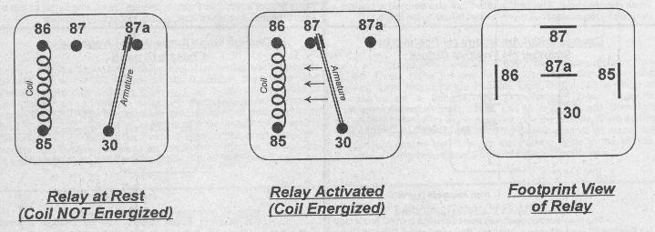
In the views above, note the five terminals, or
"pins." A relay's operation is really very simple. To understand its
operation, consider the relay as having two sections - the coil, pins 85 and 86; and the
contacts, pins 30, 87, and 87a. When Negative Ground is supplied to one end of the
coil, and Positive Voltage is supplied at the other end, the coil creates a magnetic field
which activates the relay. This magnetic field attracts the armature, which is
attached to pin 30 with a flexible joint, just like a hinge. Inactivated, or
"at rest," the armature connects pin 30 to pin 87a. When the relay is
activated, the armature connects pin 30 to pin 87. The terms used to describe the
contact points are this: pin 30 switches between pins 87a and 87, so it is
"Common" to both and is usually referred to as COM. In the relay's normal
condition, at rest, pin 30 is connected to pin 87a, making pin 87a "Normally
Closed" or NC. Pin 87 is not connected to pin 30 at rest, so its status is
"Normally Open" or NO. This type of relay is defined as "Single Pole
Double Throw" or SPDT. This term means that the single armature terminal (or
pole, pin 30) can be connected (or "thrown") to two other terminals, pins 87a
and 87. The SPDT relay is one of the most useful configurations due to its
flexibility - it can be used as a switching device, to isolate circuits, to interrupt
circuits and to interrupt and switch at the same time.
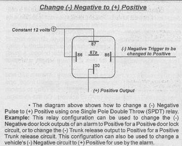
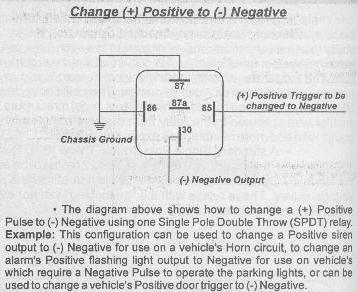
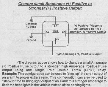
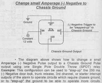
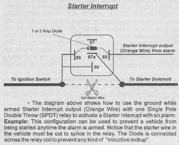
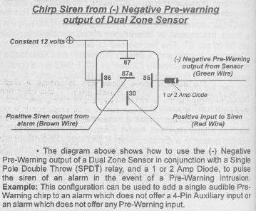
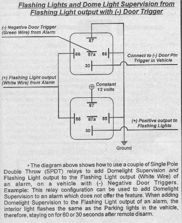
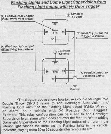
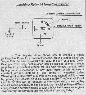
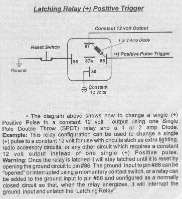
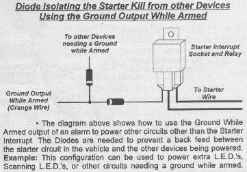
Here are some relay diagrams which show how to use
relays to perform many functions such as trigger reversal, starter interrupt, add dome
lights to flashing light output of alarm, using latching relays to change a pulsed output
to a constant output, and many other uses. These relay configurations can be very
helpful when installing an alarm, remote start, or keyless entry to perform different
functions in the vehicle on which they are being installed.
There, if you aren't a relay expert after all that,
you need help!!! :-)
Understanding Diodes
Diodes are electronic components which have the
ability to allow current flow in only one direction. There are many electrical
systems and electrical components and circuits which use Diodes to prevent a back feed
between circuits, to isolate circuits, and to prevent some current spikes. Diodes
are ideal for isolating an alarm, keyless entry system, or remote start from the factory
wiring in a vehicle.

Diodes are small cylindrical shaped components
which are consisted of two leads, the Anode and the Cathode. The Cathode is the
striped side of the Diode. Usually a Diode is black in color with a Gray stripe marking the Cathode side of the Diode.
Current will flow through a Diode in one direction
only. When the Anode side of the Diode is facing towards the Positive source of
voltage, it WILL allow the circuit to be completed, and is considered Forward Biased.
If the Cathode side of the Diode is facing towards the Positive source of voltage
(Anode towards Negative source), then the Diode will NOT allow the circuit to be
completed, it will instead prevent the circuit. According to Electron Flow, current
flows from negative to positive in the direction that the electrons flow. The
Conventional Current Flow theory seems to be the most popular and is used more often,
therefore, the diagrams in the following examples will be based on the Conventional Flow
Theory.
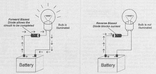
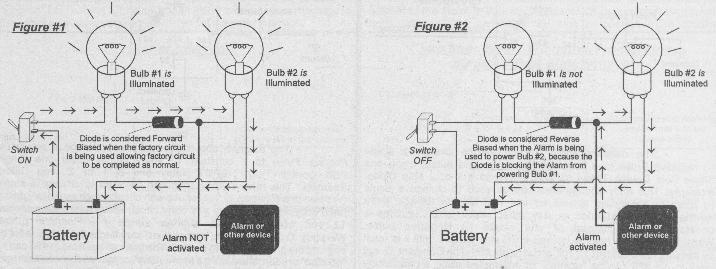
The following diagram illustrates how a Diode can be
added to a factory circuit to isolate the Alarm or other device so that, when activated,
it will power just one of the components in a circuit instead of all the components in the
circuit. In this case the Diode could actually be considered Forward or Reversed
Biased, depending on the actual circumstances of the circuit. For example: In
the circuit illustrated below, the factory switch controls both bulbs when the switch is
in the on position and the alarm is not activated. The Diode shown in Figure #1
could be considered Forward Biased because the current is flowing through the circuit when
the switch is used to power the circuit. The same Diode in Figure #2 could be
considered Reverse Biased, when the switch is off and the alarm is activated, because it
is allowing the alarm to power only one bulb and is blocking the current from back feeding
to the other components in the circuit.
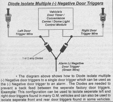
Diodes can be used in many different configurations
to perform such functions as: Using an alarm's or keyless entry's unlock output for
factory alarm arm and disarm, Diode isolating door triggers in a vehicle, using one output
to power two different circuits without back feed between the two circuits, Diode
isolating trigger circuits or components, and many other uses. For examples and
configurations of how Diodes can be used to perform these features on various different
circuits in an alarm, keyless entry, or remote start application, see the following
diagrams.
Wire Crimping
Insulated crimp-type terminals can make good
connections, but the must be done properly. Crimp terminals come in many styles, and
are sized to match wire gauge. Matching the correct size terminal to the wire gauge
is very important, and many failed crimp connections can be traced to the failure of doing
so. Insulated crimp connectors are color-coded to match the wire gauge range that
the connector is designed for. Most crimpers are also coded with matching colors to
identify the correct "nest" that the connector is squeezed in. Pink
terminals are for 20 and 18 gauge wire, and are crimped in Red nest on the crimping tool.
Blue terminals are for 16 and 14 gauge wire, and are crimped in the Blue nest on
the crimping tool. Yellow terminals are for 12 and 10 gauge wire, and are crimped in
the Yellow nest on the crimping tool. Never "shave" a wire by cutting some
of the wire strands so that it will fit into a smaller terminal. Whenever an
existing wire is being lengthened, the additional wire would be at least one wire gauge
size larger.
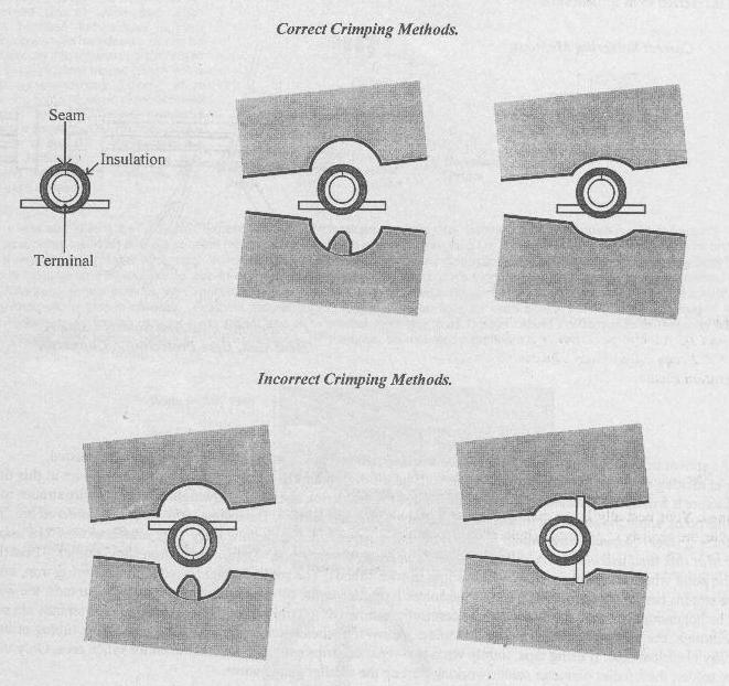
Another reason for failed crimp connectors is failing
to "crimp across the grain" of the connector. Carefully examine the crimp
area of a connector. You may have to look inside the barrel where the wire is
inserted. You'll notice a seam in this area. The jaws of the crimping tool
should be applied directly across this seam and not at an angle.
|