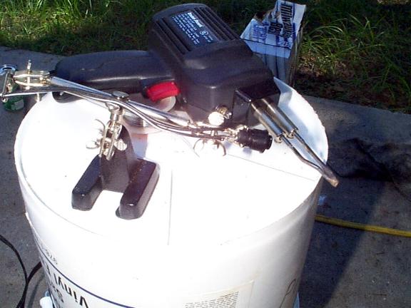
| 96 to 98 F-Body Alarm Installation Guide Section #3
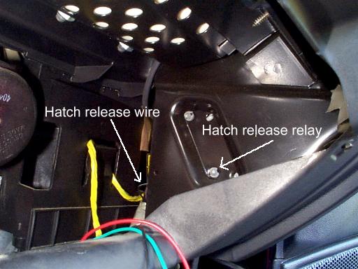
Trunk / Hatch Release Most alarms have the ability to remotely open the rear hatch via the alarm's remote if, of course, you already have an electronic hatch release... which we do :) On most cars this is a very simple connection. But, the 96 and 97 F-Bodies aren't most cars :) The BCM and its "special features" which kill power to almost all accessories after 35 seconds of the last door being closed, make us have to do a "work around" to get the trunk release portion of the alarm system to work. (NOTE: It is possible that it is not necessary to do this work around if your alarm system works in such a way as to disarm the system prior to activating the trunk release. This will "wake up" the BCM and allow a "normal" type hatch release install to work. As far as I know, all alarms do work like this but I'll be doing this install using the work around method for those who are ONLY hooking up a keyless entry system and/or remote hatch release system.) Most alarm's trunk release feature is done by sending out a negative pulse from one of the alarm's wires... usually a GRAY wire. In most cases, this wire only needs to be spliced into the proper side of the trunk/hatch release switch. But, since ours will have no power after 35 seconds, we have to splice into a different area. We will need to splice into a POSITIVE wire after the factory hatch release relay which is downstream of the BCM. This takes the nasty BCM out of the picture :) What makes this a bit of a hassle is that, if you remember before, the alarm sends out a negative pulse but we need to splice into the positive wire going back to the hatch release wire itself. To do this will require the use of a standard automotive relay (see opening page) to switch the negative pulse of the alarm to a positive pulse. The hatch release relay is located to the right of where the glove box would be and is on the other side of the plastic panel. See picture below.
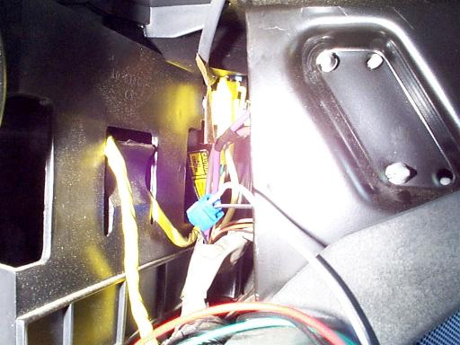
The hatch release relay is located on the back side of this panel. The arrow above is not pointing the actual relay... rather the plastic ribbed pin for the holder that is holding the hatch release relay. The hatch release wire is a BLACK wire with a WHITE stripe (BLACK/WHITE) and can be found in the cluster of wires where the arrow is pointing above. If you look closely, you'll see that I have the correct wire slightly pulled out so I can make my connection with my handy dandy Blue quick splice connector. Go ahead and make this connection now with a piece of extra wire. See picture below.
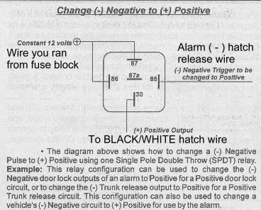
Don't forget to be checking your connections like I mentioned earlier!!! When you use your factory hatch release push button you should see 12v at this wire! OK, now for the fun part. We have to switch the output from the alarm from negative to positive. Shown below is a diagram of how this is done using a standard automotive relay.
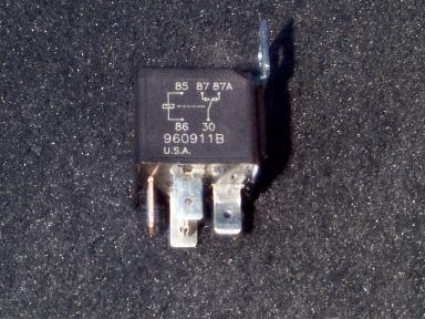
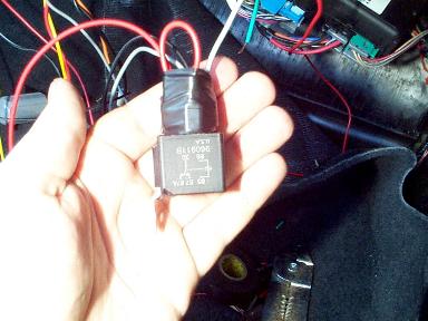
And below is what this standard automotive relay will look like. Note: not all of these relays will come with the center 87a pin. In this case, that is OK because it is not used.
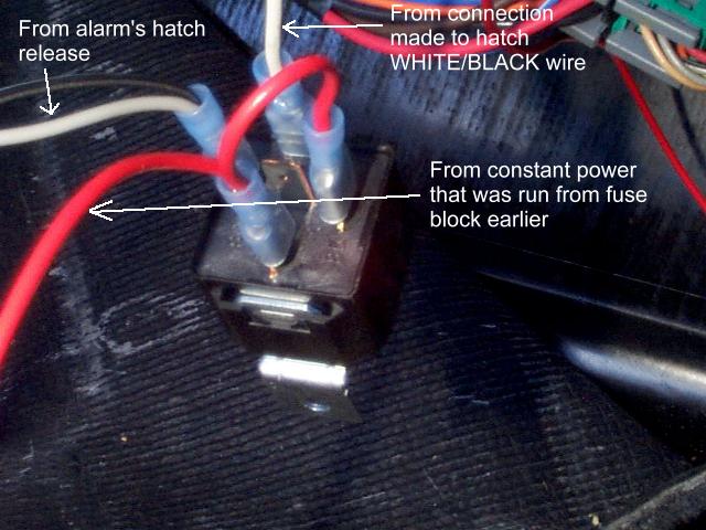
Below are what the connections will look like. I'll describe the unlabelled BLACK wire in a little bit :)
I just noticed that the way I made the connections at the relay don't match the diagram I have above :) That's OK and you can understand why if you read the opening page about relays. Real simple, for the coil connection, it doesn't matter which coil pin you connect your 12v to so long as you put the ground on the other side. You'll notice I have mine "switched" as compared to the diagram. I also have switched, according to the diagram, the ins and outs for the power to the hatch release motor. In this case, this doesn't matter because all we're doing is completing a circuit when the relay is actuated. Just thought I'd bring this up in case you're an attention to detail junkie and noticed that things didn't quite appear right in the picture and diagram. You can hook yours up like I did in the picture or as the diagram shows... it doesn't matter. (It's pretty obvious I didn't use the instructions to install this, huh? :) Even though I use insulated connectors, I'll normally go ahead and tape up the connections with electrical tape "just to make sure."
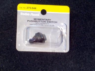
The hatch release via the alarm's remote will now work properly when we get it all hooked up! A lot of trouble just because of the darn BCM, huh? :) OK, now to describe that BLACK wire in the picture above... If it's one thing I can't stand about my Camaro it is the fact that I have to open the darn glove box to gain access to the hatch release! Call me lazy but for some reason, this just irks the heck out of me :) I must not be the only one this irks because in 97 GM moved the hatch release switch on the Camaros :-) Since it bothers me, I decided to do something about it! The rest of this hatch release section is going to describe how to install an "external to the glove box" hatch release push button... yippee! :) If you're just reading this and already have an alarm or don't want one, the following can be done as a stand alone thing. You'll just need to hook up the relay as shown above to the factory hatch release relay. You just won't be hooking up the alarm's wire... you'll have just the black wire above (or whatever color you use). The first thing to do is decide what style of switch you want to use. You'll need a momentary pushbutton switch with SPST normally open contacts. There are many different varieties of this switch at Radio Shack. I happen to prefer a switch that doesn't doesn't stand out much. You can get one that lights up or whatever you want. Pictured below is the switch I bought.
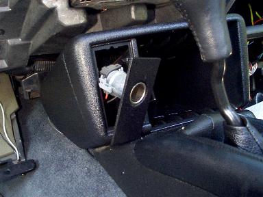
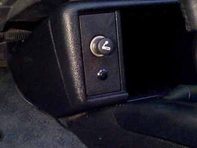
I mounted my switch in the center console panel under the cigarette lighter. It's out of the way and looks pretty good here IMO. To remove this panel so you can drill the hole, all you have to do is put your fingers in behind there until you can feel the back side of the cigarette lighter and push firmly on the back side of the lighter. This piece will pop out.
Go ahead and unplug the connector on the back of the lighter. You are now ready to drill the hole into this plastic piece. Words of wisdom here... be very careful and start with a small bit! Slowly work your way up to a larger bit. This plastic is very soft and it is very easy and likely that the drill bit will "catch" too big a hunk of plastic and rip/tear the plastic piece BEYOND where your hole will be. Meaning, it's not going to look too good. Take your time and be very careful. Hold this piece very tight while drilling the hole because if it does catch too much plastic like I mentioned above, this piece will be ripped from our hand and go twirling about on the drill bit. Sounds like this has happened to me, huh? :-) Another thing to consider with a small switch like this is that the wires will most likely need to be soldered onto the backside of the switch. If you don't know how to solder, make sure you get one that already has wires attached or that you can place connectors on.
Once you have the proper size hole drilled and the wires connected onto the switch, you can install the switch into the center console piece. What we'll be doing is sending a negative pulse to the relay to activate our newly installed relay. This means that one of the wires coming off the switch will need to be connected directly to ground (use the ground wire we made WAY above) and the other side will be connected to the other side of the relay coil as shown in the relay diagram above. With the crimps and wire I used, I was able to install both the alarm's trunk release wire and my home made switch wire into the same connector and plug it onto the tab of the relay. One thing to keep in mind here is that the safety portion of the hatch release relay is taken out of the picture with this pushbutton switch! Meaning, currently your switch "looks" at your gear selector to make sure you CAN'T open your hatch if you're going 80mph down the Interstate. This switch we just installed, if pressed, will pop the hatch at anytime! But, if you're like me, you've probably accidentally left your hatch open before and took off without realizing it. No biggie because the gas shocks on the hatch aren't made to pop open the hatch to the full open position like on some cars. They are there more to keep the rear hatch up! So, even if you do accidentally bump this switch while moving, no biggie because the hatch is not going to go flying up on you!
Oh, if you did decide to do this and you're installing an alarm, don't push this piece back in place yet. In fact don't even run your wires for your switch yet. Because, if you're like me, you'll install your alarm's flashing L.E.D. in this panel too which means you'll have to remove it and drill another hole! :)
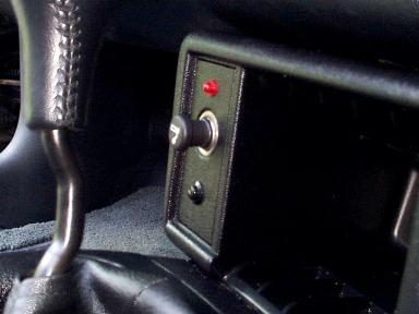
Flashing L.E.D. With most alarms, the flashing L.E.D. does many more things on top of letting others know your car is protected by a security system. Some people like these, some don't. If you don't like having the L.E.D. easily visible, then I recommend you at least install it in a location where it can be seen from the driver's seat. The L.E.D. will often tell you if the alarm was activated while you were away, what type of zone was activated, and mine even tells me how many transmitters have been programmed to the alarm. Below I show where I mounted my L.E.D. Many alarm systems will come with some type of "holder" that can be "sticky taped" to something for those who aren't too keen on drilling into their plastic panels. I, however, don't mind hacking my car up :)
If you decided to do the hatch release as I have and you're completed with it, go ahead and run these wires up to the area behind the glove box.
Valet Valet switches come in all different sizes and shapes. Some are toggle switches and others are momentary pushbutton type switches. No matter what type of switch it is, every alarm I have seen requires the ignition to be turned on for the valet switch to be operational. Without the ignition switch on, the valet switch does absolutely nothing. Most of the time the valet switch allows for disarming of the alarm (expect for the keyless entry portion and panic) for times when you take your car in for service, etc. The valet switch is also often used to program the alarm's features. The valet switch for my alarm is a momentary pushbutton switch that is mounted with double sided sticky tape.
Because it uses double sided tape, I chose to mount mine on the driver side right on the backside of the center console area where the cigarette lighter is. If yours is a toggle switch, you will probably want to mount it in a different location out of the way since it will require drilling to mount the switch. Pictured below you can see the valet switch wires just hanging down. Once you mount your switch, once again, run the wires to the glove box area.
Door Locks These would be a real bugger if you didn't have this page to guide you :) I've installed quite a few alarms and the 96 and up F-Body requires the most work arounds of any car that I have installed an alarm into. In fact, no other car I've ever put an alarm in has required a single work around except this one! What makes the 96 and up F-Body more difficult to install an alarm in than the average car is a feature known as Retained Accessory Power (RAP) which is controlled by the Body Control Module (BCM). I first got involved in the RAP and BCM problems before I even owned a 96+ F-Body. I got involved because another F-Body guy (Jason Brugger) asked for some assistance in the newsgroup alt.autos.camaro.firebird. Since I had installed many alarms in the past, I thought I'd try to give him a hand. I supplied Jason with a bunch of information about how to hook up the keyless entry feature of his alarm system. With this info, Jason made up a small web page detailing some of the install. Some of the stuff below about the door locks is what Jason wrote up with the info I gave him.
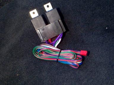
Although the wires are visible from the underside of the switch assembly, you should make your splice connections at the Body Control Module. If your alarm system does not have internal door lock relays, you may need to use external relays. Pictured below is what the relays look like that came with my alarm system.
You should see a lot of wires under here, but the door lock/unlock wires you're after will be found at the BCM in the GREEN connector to the right. See the picture below.
Splice into these using the three wire negative
instructions included with your aftermarket keyless entry or security system. Some alarm
systems do not require any relays to make the appropriate connections, but yours may
depending on the type and strength of its door lock and unlock outputs. Note:
Jason did not use relays but I did since I had an extra door lock relay harness and it
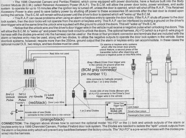
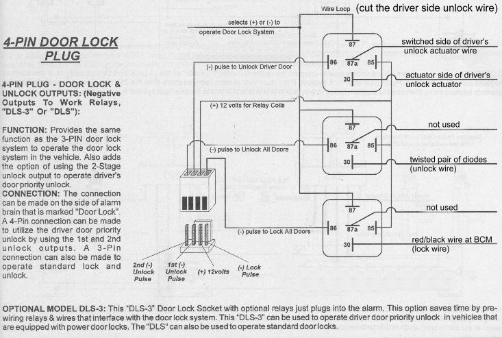
definitely can't hurt to use them. Here is a diagram of what the connection will look like if your alarm has built in relays. Pay no attention to attention to references made to specific components because yours will most likely not have the same model number for the component. Pay more attention to the labeling of the wires.
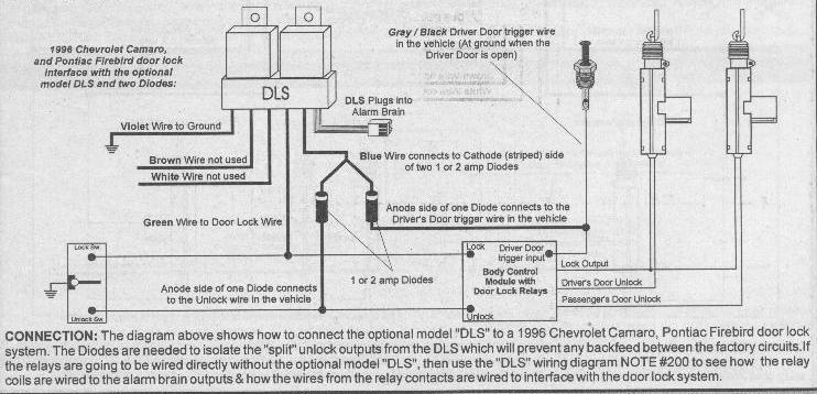
Below is a diagram of what it might look like if you are using relays. The DLS is what is pictured in the actual digital picture I took above.
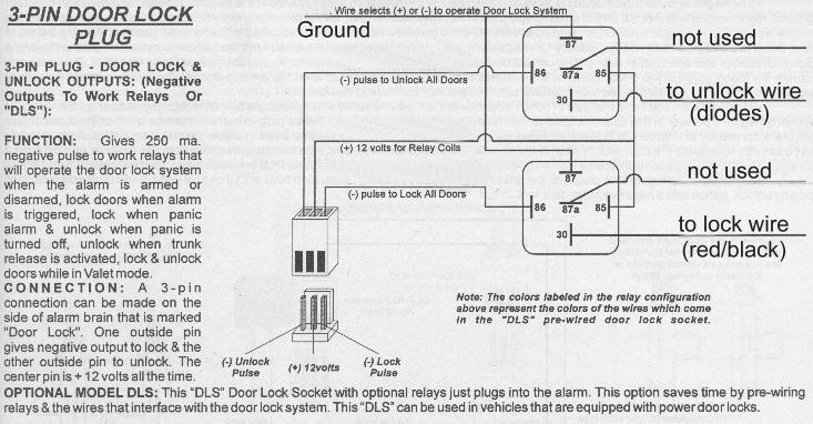
If you don't happen to have a pre-wired setup (like I do) or internal relays for your alarm, you will need to make the connections to the relays "manually" with female blade type connectors. If you need to do this, I've provided below how to make the connections to the different pins on the different relays. The first diagram is for an alarm which has three output wires for its door locks but no relays. One wire will give a ( - ) unlock pulse, the second wire will give a ( - ) lock pulse, and the last wire will be a 12v output. If your instructions indicate your alarm is like this, this will be the diagram you will use. Once again, pay no attention to specific component model number references as yours will most likely be different. I have modified the diagram with the specific connections necessary for your F-Body... it doesn't get any easier than this!!! :-) The second diagram below is for a system with four output wires. This is similar to the factory F-Body keyless entry system in that the purpose of the fourth wire is to provide a second pulse for separate unlocking of the driver on the first press of the alarm transmitter button and then on the second press of the button, the passenger door will unlock. I personally think this is a pain in the butt, but will provide SOME of the information on how to hook it up in case you happen to like it :-) This is a real pain because you have to find the specific driver side lock actuator wires... probably in the door itself... way more trouble than I'm willing to go to. Here is the first diagram which 99.9% of you will use IF you don't have internal alarm relays and IF you don't have a special pre-wired harness like I do. Which means, only a very small percentage of you will actually need to even look at the following diagram :)
Here is the second diagram I mentioned above. This is to hook up driver side priority unlock... similar to the F-Body factory keyless entry system. I doubt seriously any of you will want to do this but if you do, here it is! :)
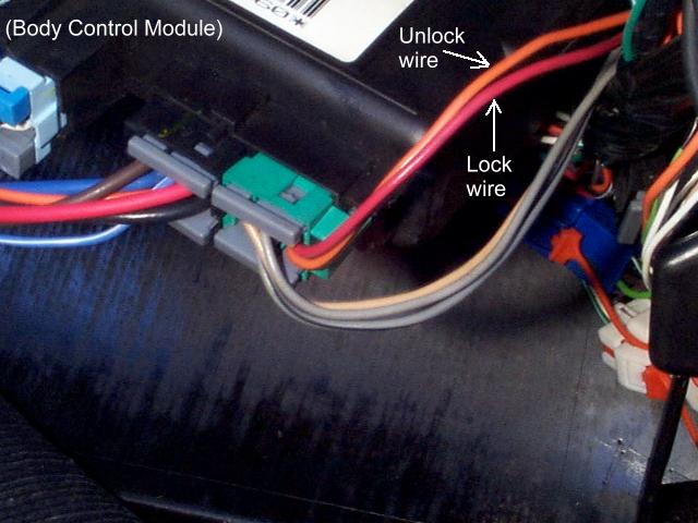
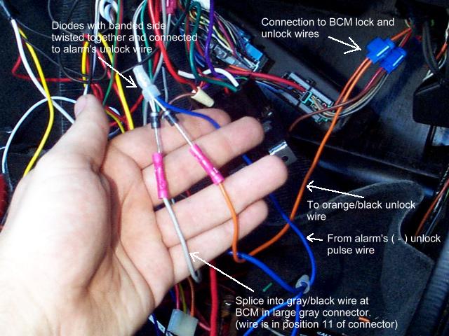
Here is a quick run down of the connections: It's a three wire negative system. The alarm wire (or relay configuration) that sends the ( - ) pulse to lock the doors gets connected to the RED/BLACK wire located in the GREEN connector at the BCM. The alarm wire that sends the ( - ) pulse to unlock the doors gets connected to the twisted banded side of the two diodes. The other end of one of the diodes goes to the ORANGE/BLACK BCM unlock wire. The other end of the other diode goes to the large connector on the BCM and gets connected to the GRAY/BLACK wire in location 11 of this connector. See the picture below.
Side Effects OK, I'm back now :) Most of the text above was
written by Jason with me throwing in a few things here and there along with the diagrams
and pictures. I liked the way Jason explained this, so I kept it mostly in his
words. If the above confused you, sorry :) I tried to make it as easy as
possible and explain it as best I could. Don't blame me that GM put in all this
"stuff" to make alarm installs more complicated than they should be! If
you did get confused and don't understand what I was trying to explain, send me an email
|