| 96 to 98 F-Body Alarm Installation Guide Section #2
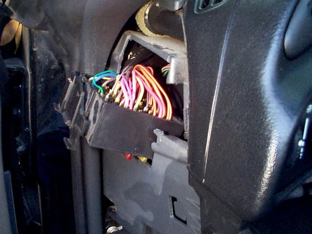
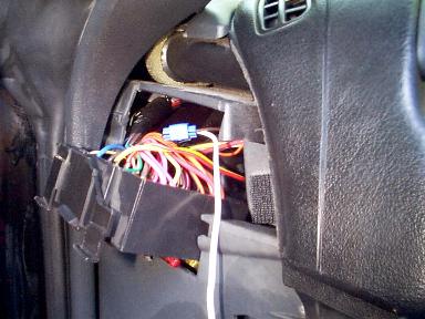
Alarm Power Wires Now is a good time to run the power wires for the alarm and other alarm accessories. You need two types of power for your alarm. You need a constant 12 volt positive supply and you also need a switched 12 volt positive supply via the ignition or accessory switch. There are a number of different places where you can "pick up" this power in the car. For example, you could get both these power supplies from behind the radio or at the ignition switch. You could also just plug in a couple blade type terminals to the front of the fuse block where there are special places for BATT and IGN just for blade terminals. But, since this is for alarm, it probably isn't a good idea to just plug your alarm's power wires into the front of the fuse block... it makes it too obvious :) I choose to connect my power wires to the back side of the fuse block because 1) it's not obvious and 2) it provides for a fused power source (25 amps). So, there's a good chance you'll have "double" fused protection because your alarm is most likely also fused. Which brings up the point that, if you're really paranoid about the car getting stolen, the thief could just start pulling fuses until the alarm quits going off. But then, he'd have to use a flatbed to take it away and hopefully by then somebody would notice something unusual was going on. Also, many alarms feature a battery backup so if yours has this feature, no need to worry :) It's a bit tricky to get to the back side of the fuse block. You have to remove one 9/32" screw and then kinda finagle the fuse block to a position shown below.
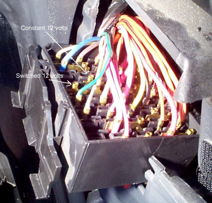
With the back side of the fuse block exposed, you can now make your connections. There are a couple ways to do this. Take a look at the picture below.
You'll notice that there are two "empty" wire connectors. It just so happens that one of these is a constant 12 volt supply and one is a switched (ignition) 12 volt supply. I choose to solder my wires to these empty slots. If you are not comfortable with soldering, you can use BLUE quick type splice connectors. They can be purchased from places such as Wal-Mart or Radio Shack. I'll use them later on down this page. If you do want to use these now, take a look at the above picture to see where the constant and switched power sources are. You should see that the YELLOW wire on the back side of the fuse block is where you want to connect your alarm's Ignition/Accessory wire. You should also see that the ORANGE wire is where you want to connect to for a constant power source (BATT). Throughout this page, I'll be using "chunks" of other wire I have laying around to make the initial connections like below. What I mean is the wires that I have soldered to the fuse block below are not the wires from the alarm's wiring harness. I prefer to use a different piece of wire then run all these wires to the alarm brain. I'll then make the connection at the alarm brain to the proper wire in the alarm's wiring harness. I do this for a couple reasons 1) personal preference and it's usually easier to route the wires through the car and 2) most times the wires on the alarm's wiring harness aren't long enough :)
Parking Lamps Most all alarms provide an output that will flash the parking lamps when the alarm is armed, disarmed, or set off. Most alarms have an internal relay and this line is fused. Check your alarm to see how yours is setup. You *may* need to hook up an additional relay if your alarm doesn't provide for a "direct" connection to the parking lights. The 4th Gen F-Body has an easy connection for flashing the parking lamps. Connecting to one wire will allow all the parking lamps to flash and also the driving lights if they are turned to the on. This connection will be made to a Positive 12 volt wire so ensure your alarm's output for this feature is also +12v. This wire is a BROWN wire and comes off the headlight switch. This wire runs behind the fuse block and is accessible when the fuse block is removed (which is why you're doing this now before you re-install your fuse block! :) There is more than one BROWN wire coming off the light switch assembly. Make certain you get the BROWN wire coming off the MAIN headlight switch. If you are having trouble determining which wire to connect to you may need to remove the three 9/32" screws which hold the dash trim down. Removing these three screws will allow you to slightly lift the dash trim so you can get a look at the back side of the switch. You'll also need to take a razor blade and cut the electrical tape away from the cluster of wires behind the fuse panel going to the headlight switch so you can see the wires! Once you get all this done, you can use a BLUE quick splice connector to splice into this BROWN parking light wire.
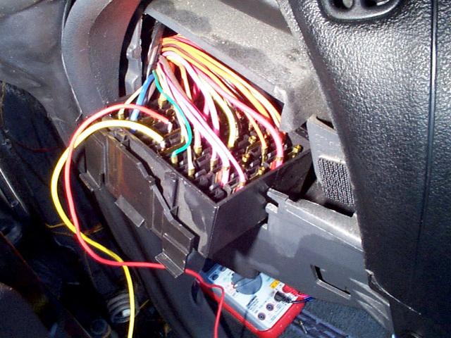
Now that you have made your connections for the alarm's power wires and the parking lamps, you can run these wires through the opening that you can see in there to the center somewhere near the steering column. Once you have these three wires run, go ahead and reposition your fuse block and re-install the screw. It's also a good idea to, if possible, check your connection by using a meter or test light and turning on your parking lights. If you have 12v at the end of the wire you connected, you're in good shape! If you don't you either got the wrong brown wire or your connection isn't good. It's also a good idea to check your constant 12v and switched 12v power supplies using the same method. For the rest of this page, "test" all connections where possible, i.e., if you are hooking up a ground, find a 12v source and use your meter, this 12v power source, and your recent ground connection to see if the ground you just made is good.
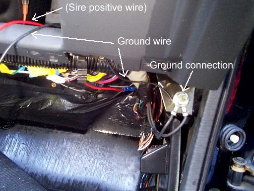
Ground (negative) Your alarm and many alarm accessories also need a connection to ground. It just so happens that there is a really nice connection staring you in the face on the passenger side. See the picture below for location. Once again, I've used an extra piece of wire I had laying around for this connection. I have a lot of wire laying around and you'll notice that I'm often able to match colors for my particular alarm... white wire for parking lamps, red wire for 12v, yellow wire for switched 12v, and now the black wire for ground. This isn't really necessary, but if you can do it, it will help you to keep all your wires in order and it's less confusing later when you go to connect everything to the alarm :)
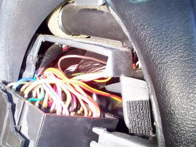
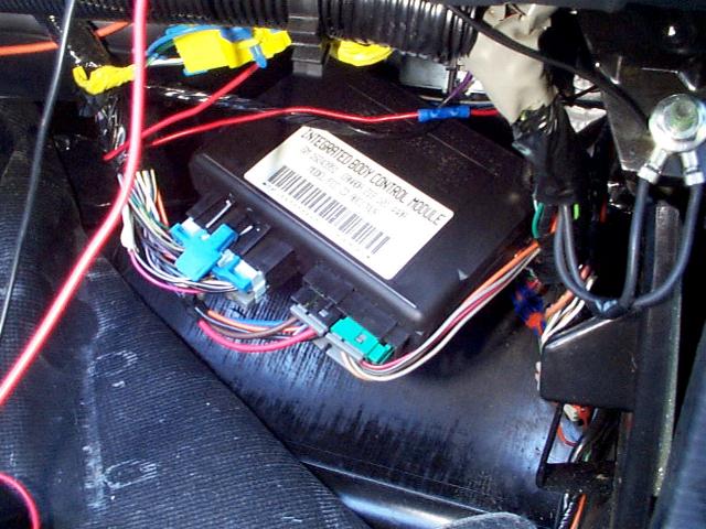
Body Control Module (BCM) As I mentioned before, the BCM is an integral part of the alarm installation. Since we'll be making a number of connections to the wires going into and coming out of the BCM, there is no sense fighting it tucked up under the dash like it is. It's now time to pull it down out of its holder. It is not held in by any screws or anything. It is more "wedged" up in there. It takes some fighting and prying on its holder to get it to come down. After playing with it for a minute, you'll see what is holding it in place and you'll be able to pull this plastic apart so it will "release" the BCM and allow you to pull it down. Pictured below is what you'll have once you get the BCM pulled out of its holder.
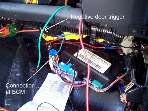
Negative Door Trigger Most alarms will have an input for a Negative Door Trigger, a Positive Door Trigger, and a Negative Instant Trigger. Your F-Body uses the Negative Door Trigger input on your alarm. You will not even need to use the Positive Door Trigger. The Negative Instant Trigger is there if you want to use more pin switches (usually supplied with the alarm). I rarely install more pin switches. The two doors and rear hatch are all covered using the Negative Door Trigger wire as shown below. What is not covered is the hood. This doesn't bother me and I don't worry about it. This is a perfect example of how you would use the Negative Instant Trigger of your alarm. You would install the pin switch to protect the underhood area of your car then run the pin switch wire to the alarm's Negative Instant Trigger input wire. Then, when somebody opens the hood with the alarm armed, it sends a ground (negative) through this wire and triggers the Negative Instant Trigger of the alarm. If you think somebody can get by the door pin switch and the shock sensor to gain access to your hood release, then by all means, feel free to install a pin switch under the hood :) Actually, it's probably not a bad idea and won't hurt a bit if you want to install a pin switch under the hood. I guess I'm just too lazy :-) Anyway, there is ONE wire you can connect to that will cover all three entry points (two doors and rear hatch) into your car. This wire is a WHITE ( - ) wire and is located in slot D1 of the large 32 pin connector at the BCM. This is the interior courtesy lamps return wire. So long as the BCM is awake and active (see door lock section for in-depth description of this) anytime a ground is seen on this wire (via the pin switches for example) the BCM sends 12v to the interior lamps which will light them. See the below picture.
Dome Light Supervision If your alarm has dome light supervision, you will connect this wire to the negative door trigger wire we just installed shown dangling above. If your alarm does have dome light supervision, it probably has two wires of the same color for this feature. One wire most likely is fused. The reason for the two wires is it allows you to utilize this feature whether or not your particular car takes 12v or ground to activate the dome lights. Our cars take a ground, which is the reason we're connecting into the negative door trigger switch :-) The connection is as follows: Connect the alarm's dome light supervision fused wire to the ground wire we made earlier. Connect the alarm's other dome light supervision wire (non fused) to the Negative Door Trigger wire you installed above. IF your alarm does have dome light supervision but it doesn't provide for two wires like I mentioned above, then ENSURE that its output is negative/ground! If it is, all you will need to do is connect this wire to the Negative Door Trigger wire.
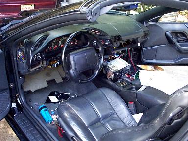
Take a Break! :-) At this point, if you're not used to doing this kind of work, you may be feeling a bit overwhelmed with half the interior of your car all torn apart :) Kick back, have a beer (or soda :) and relax. We're getting there!
Oh, you won't need to pull your radio out. I was having trouble finding the hatch release relay... it's not behind the radio :-) OK, back to work!
|