| 96 to 98 F-Body Alarm Installation Guide Section #4
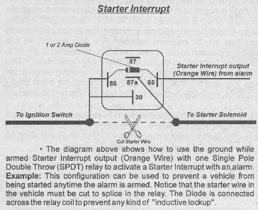
Starter Kill OK, there is the conventional starter kill and then there's my starter kill :-) First off, I'll tell you about the conventional starter kill. Most of the starter kills are "neat" in the way they function and are very reliable. Starter kill circuits use standard automotive relays. What I mean by "neat" is normally you would think of a relay as being either energized or de-energized i.e., when the alarm is activated the relay is energized and when the alarm is de-activated, the relay is de-energized (or vice-versa). If this were the case, the failures of alarm starter kill relays would probably be much higher because this relay would be energized say 1/2 the time. This could also cause your battery to go dead if you let the car set for extended period of time due to the small current draw by the relay when activated. Well, this is not at all how they work. Study the diagram below.
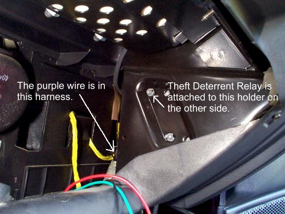
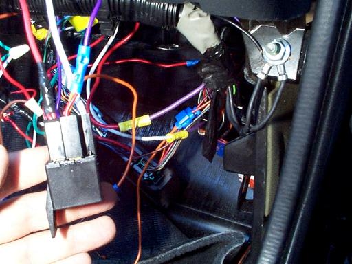
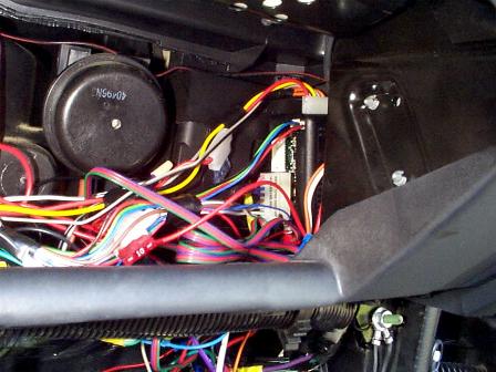
If you read my opening page and learned anything from it, you'll see exactly what the above relay configuration is doing for you :) But, if you didn't, I'll try to explain it for you :) Pins 85 and 86 are for the coil. The starter interrupt output from the alarm is connected to pin 85. This wire from the alarm is nothing more than a ground signal whenever the alarm is armed and an open when it is not armed. Pin 87a goes to the starter and is where the relay's armature rests when the relay is de-energized... the electrical path is completed from pin 30 to 87a when the relay's coil is de-energized. Now, instead of supplying a constant 12v to the other side of the relay, you'll notice that this 12v supply is coming from the ignition switch. Since this is the actual starter wire, it is only getting 12v when the key is turned to the start position. So, with the alarm disarmed, if the key is turned to the start position, the relay doesn't actuate because there is no ground from the alarm (alarm disarmed). But, if the alarm is armed, and the key is turned to the start position, the starter wire will get 12v up to the point of the relay. When this happens the relay will actuate (since a ground is being supplied by the alarm to the other side of the coil) and will "pull" the armature of the relay to pin 87 and thus breaking the starter's 12v circuit from pin 30 to pin 87a and not allow any "juice" to go to the starter. With this type of relay configuration, the only time the relay will be actuated is when someone tries to start the car with the alarm armed... which should be NEVER! :) Because of this design, starter interrupt relay failures are basically nonexistent. To connect this up to your F-Body, it seems most install books reference using a YELLOW wire at the ignition switch. Well, since most alarm installers connect the starter kill here, this is exactly what the thief is expecting and looking for. I happen to have a factory service manual for the 96 F-Body and have found a much better place for this connection :) I prefer to use a PURPLE wire which is downstream of the theft deterrent relay. This wire is in an unsuspecting location on the passenger side right before it goes through the firewall and is difficult to get to. A perfect place! What makes this even better is that you already have the car torn apart to the point it needs to be to get to this wire! If you remember above from the hatch release, this theft deterrent relay is right above the hatch release relay in the glove box area. See picture below.
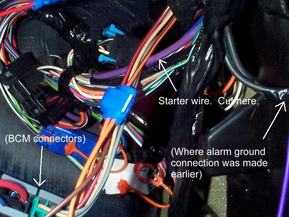
Now that you've found the relay you're probably noticing that it is a pretty tight working area back there. Never fear, there is a better place to cut the PURPLE wire and make your connections. See picture below. To give you a reference of where this is at, I've labeled a couple things you are already familiar with.
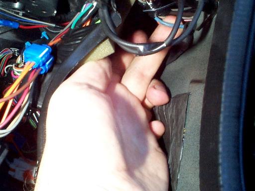
OK, now that I've described how to do the conventional starter kill, I'm going to show you my way to do the starter kill. If you think about it, if the thief can disable your alarm, and can get by the PASS Key protection (which some can) then he has the ability to start your car. Many of the high tech thieves use code grabbers that can actually intercept the frequency of your transmitter. They'll then use their "special device" to disarm your alarm when you walk away from the car. Say bye bye to the F-bod. What I've done is installed a starter kill type circuit which is completely separate from the alarm system. It is stand alone and does not need the alarm system. It is extremely simple yet extremely effective. This works on the complete opposite theory of the conventional starter kill I described above. I still use the same PURPLE wire (much better IMO than the YELLOW wire at the ignition switch!) but in my circuit the only time the circuit to the starter is completed is when I want it to be. Here is how it works... when you get in my car and turn the key to the start position, nothing happens. It doesn't matter if the alarm is disarmed or even if you have the right/wrong key... nothing will happen period. In order to start my car, I must hold the driver side passenger window switch in the UP position WHILE turning the key to start the car :-) I decided to use this particular switch for a few reasons 1) I didn't want an extra switch which appeared out of place or suspicious 2) I needed a switch that I could access with my left hand while turning the key with my right and 3) The connection for this wire is right near our PURPLE wire! What this does is activates a separate relay I installed any time the passenger window switch from the driver side is pressed in the UP position and there is power available to the accessories. What this also means is that the relay won't be made up unless the key is turned to the ON position even if the switch is held in the correct position. We're talking multi levels of protection here. So basically, if anyone ever steals my car, it has to be one of my friends or one of you guys reading this page :-) The chances of somebody getting by 1) my alarm system 2) the PASS Key II system and 3) my super secret window start is highly unlikely :) You're probably thinking right now that this relay will be made up whenever you roll up your passenger side window. Well, you'd be correct, but so what? :) All that is happening is the relay is being made up. There is no power being sent through the relay (except for the coil, of course) because you're not holding the key to the start position. About the only extra thing you need to know in addition to the above conventional starter kill information is the location of the correct wire for the passenger side window roll-up. This wire is a LIGHT BLUE wire and can be found in the wiring harness just before this grouping of wires exits the car and goes into the door. This is pretty much a pain to make this connection but isn't too difficult if you use a blue quick splice connector. Pictured below is the wire you'll need to connect to if you choose to do this type of starter kill.
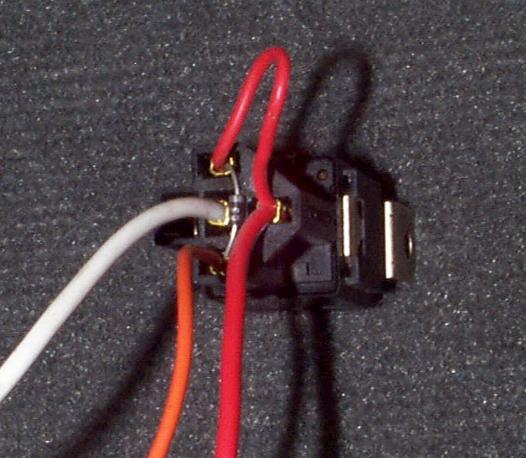
Once you make this connection with a piece of "spare" wire, we're ready to make the rest of the connections to the relay. Go ahead and cut the PURPLE wire as described above in the conventional starter kill section. For this starter kill I just used a regular starter kill relay harness (pictured below) and modified it slightly by snipping the red "loop" since we want the 12v that powers the coil (window up 12v) to be different than the 12v coming from the ignition switch and also by taking the white wire shown below and moving it from its center location (87a) to the blank left slot (87). How necessary is the diode? I don't really know. I'm sure it's there just as a precaution. If you don't have a harness like this, you can use regular female type blade connectors (like what would slide over a speaker connection) and slide them over the individual relay posts. These can be found at Radio Shack or even Wal-Mart. The diode you'll probably have to pick up from Radio Shack.
NOTE: The following will describe connecting
wires to the relay pins based on the above picture of the relay harness that I used.
This picture is different than the scanned in diagram near the top of this page!
The coil pins (85 and 86) are "swapped." By that I mean the diagram
shows pin 86 being 12v whereas I have pin 86 being a ground and pin 85 being a ground
where I hook it up to 12v. This is OK so long as you get the orientation of the
diode correct... the banded side must point towards the 12v side, regardless of which pin
you use for 12v. Don't let this confuse you. Either follow the diagram at the
top or the below paragraph but don't try to combine the two because you will get confused!
:)
The more I think about this type of starter kill, I believe it to probably be more effective at preventing your car from being stolen than the entire rest of the alarm system combined. The nice thing about this is that you can get protection like this for under $5 (the cost of the relay and a few connectors) and all you have to do have is a little mechanical skill and be able to follow the instructions I have above. I don't know how many people actually do "weird" and different type stuff like this, but I welcome your comments. Send me some email if you've done an "off the wall" install like this and tell me about it - bfranker@citrus.infi.net Heck, I'm going to make up a separate page detailing how to do JUST this type starter kill since you don't need an alarm system to do it :-) I'll also throw in that if you like this type idea for a starter kill but are SUPER paranoid, there is no reason why you can't wire a starter kill like this up in series with a conventional starter kill. All you'll need is another relay.
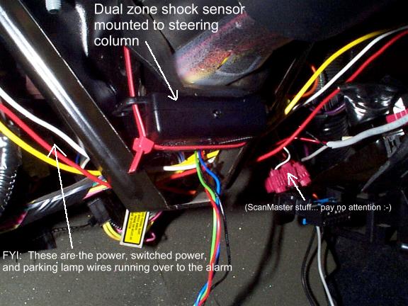
Shock Sensor Mounting This is an extremely important part of the alarm install. The shock sensor and its adjustment can cause a ton of aggravation for you if you don't get it adjusted or mounted properly. It is important to mount the shock sensor to a good solid surface. I will most of the time use the steering column for the mounting location of the shock sensor. The steering column works well to pick up vibrations coming from all sides/areas of the car. It also doesn't amplify certain areas. If you start getting a ton of false alarms, it's most likely due to how you mounted the shock sensor or how sensitive you have it adjusted. Many people seem to judge an alarm by how many times it will give a false alarm. Let me tell you, this is MOSTLY due to the installation and/or adjustment and not the alarm itself. I don't care if you have a $50 alarm or a $1000 alarm, if the $50 alarm is installed properly it will perform similar to the $1000 alarm but maybe not have all the bells and whistles. FYI: I use high quality dual zone shock sensors and dealer cost on these is around $20. My alarm system is a top of the line alarm system and came with a high quality dual zone shock sensor and has almost every feature you can think of on it and dealer cost on it is under $100. What I'm getting at here is you can save a TON of money by installing an alarm yourself and you don't necessarily need a $500 or $1000 alarm :-) Anyway, back to the topic at hand, the shock sensor. I mounted mine on the steering column as shown below.
You'll notice that I mounted mine with tie-wraps. This is 'OK' so long as you can get the shock sensor mounted tightly and securely. Depending on the size of your shock sensor, you may or may not be able to mount it in this location. If your shock sensor is too big for here, just find another metal area that is sturdy and connected to the rest of the vehicle. Don't forget to mount it in such a way as you'll still have access to the adjustment screw(s)! You'll be adjusting that in a little bit.
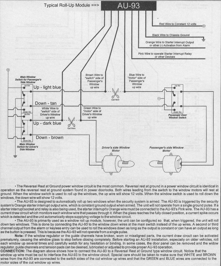
Window Roll-Up My windows roll-up module is still sitting on the shelf waiting to be installed ;) But, even though I have not yet connected mine, I can give you some guidance on how to do it. There won't be any pretty pictures, but you should be able to figure out how to do it :) The window circuit in the 96+ F-Body is a Reversal Rest at Ground system. Check your instructions and you should see similar wording. What this means is that when you hook up your window roll-up module you won't be splicing in the wires; you'll actually be cutting the wires in the car and hooking them to the windows roll-up module's wires. I'm not going to have ideal locations for you to cut the wires at because I have not yet done this on my F-Body myself. My book tells me the place to make the connections is at the driver side switch itself. This means you'll have to run a number of wires into the door itself. I have to believe there is a better place but until I actually do this myself, I'll have to rely on the information I have. Pictured below is a diagram for the Reversal Rest at Ground system. Once again, ignore specific references to model/part numbers. Pay attention to only what the particular wire is doing and convert it to your particular window roll-up module. I have, although, modified the diagram to show you the necessary F-Body window motor wire colors. The driver's side wire color for up is: DARK BLUE and down is: BROWN. The passenger side for up is: LIGHT BLUE and down is TAN.
Once you get your window roll-up module wires hooked up, you'll need to run at least one of the wires to the alarm brain so the roll-up module knows when to roll up the windows! This is usually a wire that will go to the same wire as your starter interrupt wire but check your instructions just to make sure. Run the activation wire now to your alarm brain which will be behind the glove box.
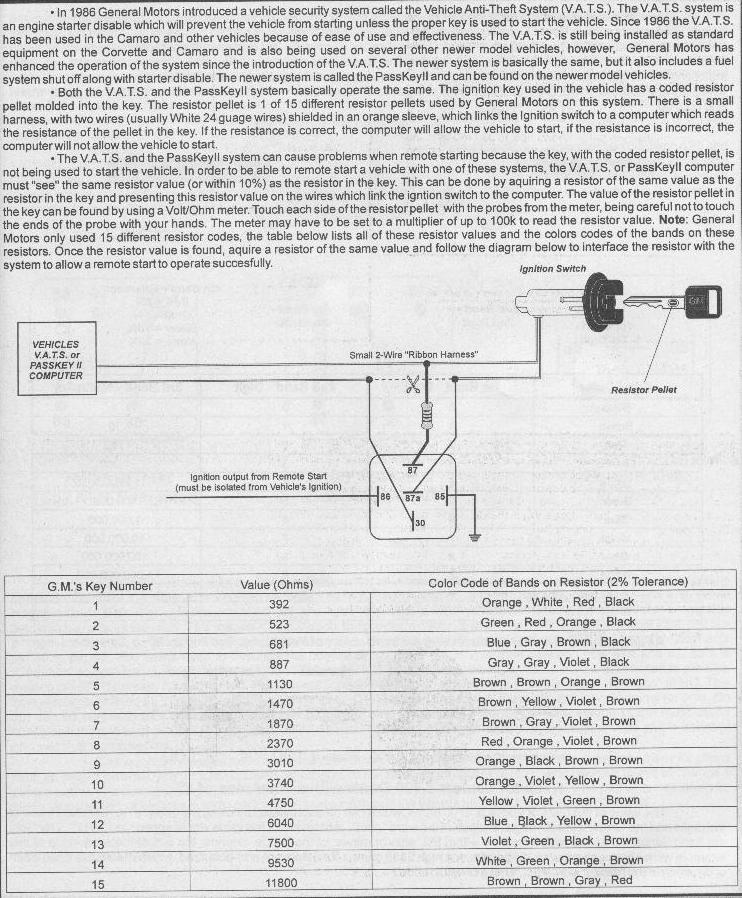
Remote Start Connecting up a remote start is a bit tricky because you have to temporarily bypass the VATS, PASS Key II system. This isn't difficult if you know how to do it :-) You also probably don't want to connect up a remote start to a standard transmission F-Body. To do so, you'd have to over-ride the clutch safety switch. Doing so would mean that you would need to always ensure that when you parked the vehicle that you placed it in "N" and set the parking brake. Failure to do so will destroy whatever is in front of your car and also the front end of your car! For this reason, I recommend only connecting a remote start to an A4 F-Body. Connecting up a remote start is almost like connecting another entire alarm system because there are so many wires :) Unfortunately, my remote start system is still setting on the shelf in the garage so I have no first hand experience installing one of these in a 96+ F-Body. All I have is the information form my install book which I'll pass along here. The first thing you must do is get around the PASS Key II system. The PASS Key II system uses 15 different resistor pellets (located in the key) to determine if the proper key has been inserted or not. We have to temporarily bypass this system to allow for remote starting. This means that you'll need to know the code of your key. The easiest way to do this is to stop by a local locksmith or your local GM dealership and ask them to insert your key into a special little gadget and tell you what number (1-15) key you have. If this is not convenient for you, you can measure the resistance across the key's pellet and cross reference it to the closest value below.
With the above diagram and also the locations for the various wires listed at the top of this page, you should have enough information to be able to install a remote start system. Just remember to follow the directions closely on your remote start system. When you get everything connected, you'll need to run at least one wire to the alarm brain. Run this wire now.
Connecting the Wires Wow! You're just about done! We've mounted and installed all the goodies and run all the wires to the area behind the glove box. All that is really left is to make the connections to the alarm wires and mount the alarm brain back out of the way! This is the easy part! :-) There really isn't a good way to describe how to run all those darn wires and make them look "pretty." I normally will always give myself extra wire because I absolutely HATE being a couple inches short :) For this reason, I tend to have a bit of extra wire at the alarm brain when I get everything connected. This is OK IMO. I'm not trying to win any awards on how "pretty" my install looks. No one is ever going to see any of this anyway (well, except for the L.E.D.). So, as long as all my connections are tight and the things I installed don't rattle while driving, that's all I really care about. Go ahead and make all your connections to the alarm system now. If you connected everything properly, your alarm should start blaring when you plug in the main harness to the alarm or connect the power lead. If you connected something improperly, you might need to make a trip to Wal-Mart to pick up some extra fuses! You'll also find that now is the time when, if you didn't label all your incoming wires, or use different colored wire like I did, you'll wish you had! Once you get everything connected, test out the alarm and play with it a bit to make sure everything works. It's also a good time to adjust the sensitivity of your shock sensor. I made all my connections so I would have enough wire so I could place my alarm behind the glove box and behind where the Theft Deterrent Relay and Hatch Release relay are. See the picture below. You can spend hours making every wire look pretty and perfect, but I choose not to do this :)
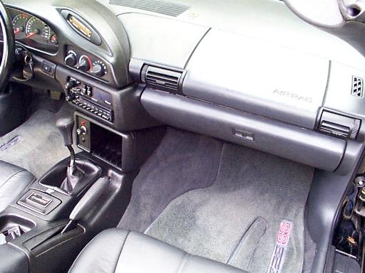
Once you get everything working properly, go ahead put the brain behind the glove box like shown above and reinstall all the interior panels that you removed earlier. It should look something like the below picture when you're done! I bet you thought you'd never get your car back to looking like it did before :) Notice below that I did in fact get everything back together and the only indication that I took everything apart is the little alarm L.E.D. light on the center console :-) It can be a bit intimidating when you see everything ripped apart like that. I've installed numerous alarms for friends and a couple of them almost fainted when they came out to see how I was doing and check on my progress :-)
Well, that's it! If you're not an electronics guru or hands on junkie and decided to tackle this job yourself, give yourself a pat on the back! The intent of this enormously large and carried away web page was to give the complete novice a chance to tackle a job like this on his/her own. I've guided a number of people through email on how to hook up specific parts or their alarm system but have never gone to this level of detail. I certainly hope you got some use out of this page. This whole page may seem a bit overwhelming, but if it's any consolation, it took WAY WAY longer to make this page than it did to do the actual install :-) Heck, if you read the whole thing and don't ever intend to install an alarm system, maybe you learned a little about your car :-) Either way, I'd love to hear some feedback from you! My F-Bodies are my hobby and so is the computer so I try to combine the two :) If you have any comments, recommendations, enhancements, find typos, whatever, please let me know! My email address is listed below.
|