| The first thing you have to do is gain
access to the rear of the air conditioning vent. There are two small plastic clip
things that hold the vent in place. You have to gain access to the rear of the vent
in order to push in at least one of these clips so the vent can be removed. In order
to do this, you have to remove a few plastic panels first :) 1. You have to pull down your glove box. The way the glove box
stays "up" is kinda cheesy :) To drop the glove box open it and you'll
then notice that it is held there from falling by plastic "ears" on the back
side of the glove box. Just take the side of the glove box compartment and push it
towards the center. You'll notice it start to cave in a bit at which point you can
pull that ear over the piece that it catches on. Do the same for the other side.
This allows access to the three 9/32" screws for the radio trim. Remove
these three screws.
(All the small pics on this page can be "clicked" to
view a larger image)
2. You now have to remove the panel under the steering
column to gain access to the other side of the radio trim piece. This is held in
place by two Phillips head screws and two 9/32" screws on the bottom side. Go
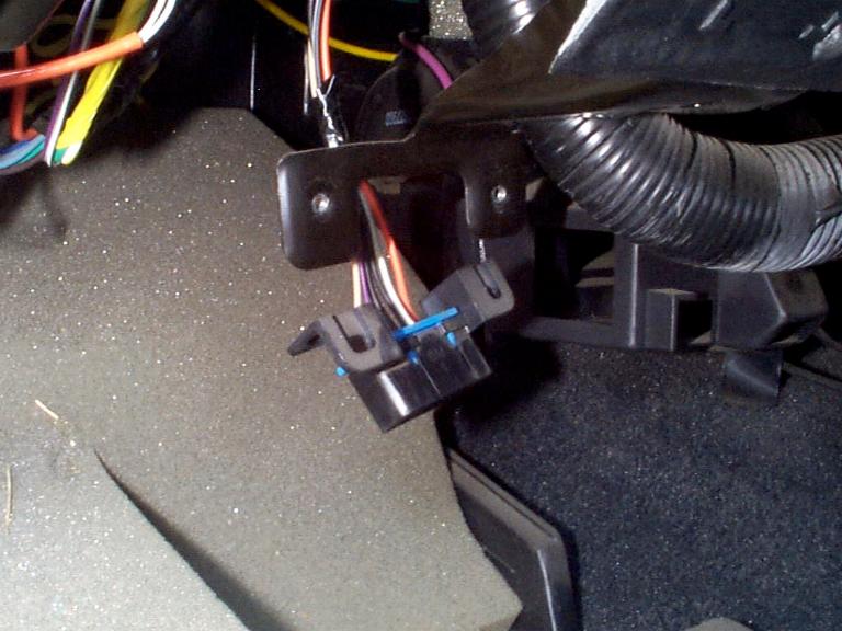
ahead and remove these. If you have a rear window defroster as I do, you'll have to
unplug this connection once you pull this panel partially away. To do this remove
the white clip as shown below to the left. On the right are the other two
9/32" screws that need to be removed to remove the radio trim. Remove these and
pull off the radio trim piece.
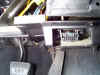
3. OK, there is only a couple more screws that need to
be removed to gain access to the back side of the vent. A lot of work just to get to
little air conditioning vent, eh? :) One is on the left side of the gauge cluster
trim and two below this trim. This allows you to "lift" the trim around
the gauge cluster. My original intention was to remove this piece but in order to do
this, you have to remove the entire flat dash plastic piece that extends to the
windshield. This isn't a big deal because it's just snapped (or Velcro held) in
place. My problem was I couldn't get one of the snap things to snap loose right
behind and to the left of gauge cluster. If you can get this dash piece off, you can
gain access to a couple more 9/32" bolts and you'll be able to completely remove the
instrument cluster trim. This would make things easier to work on but as you'll see
in upcoming pics, I just held the gauge cluster piece up and out of the way. It was
a bit tight, but it was doable and it beats me breaking my dash trying to take it off :)
Anyway, here are pics of the screws you need to remove, at a minimum. If you
can get your flat dash piece off without trouble, go for it! I couldn't :)

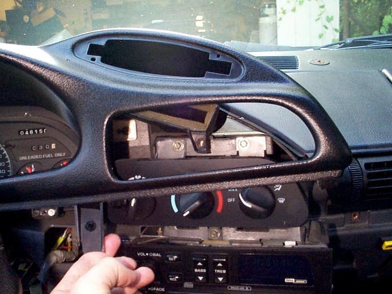
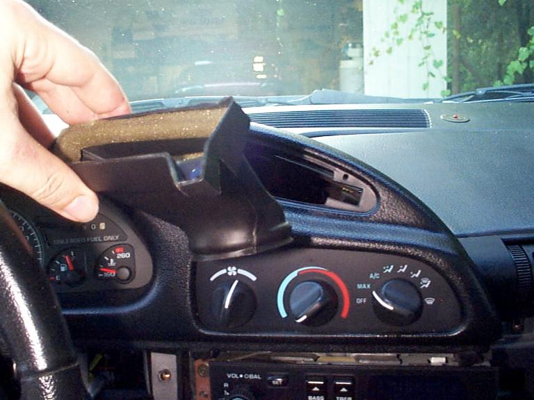
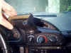
4. Now that all those darn trim pieces are removed, it's
time to get to work! Now that you can move the gauge cluster trim piece, go ahead
and lift it up as shown below. This doesn't look like much, but this is all I had
and is all that is really needed for what we need to do. Be careful not to scratch
your air conditioning control knobs! (I already have the vent removed in the pic :)

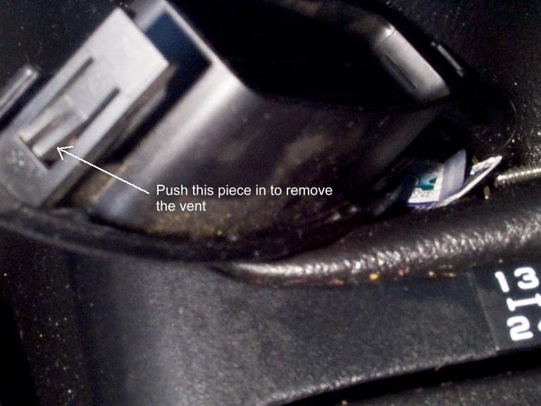
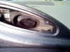
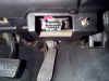
5. Once you have it pulled out like this, you can reach in
from the right and feel a small clip on the side of the air conditioning vent. Just
push in on this clip piece and at the same time push that side of the vent out. This
will pop loose one side of the vent. It will just pull out now. Below is a
picture of what the clip thing that you need to release looks like. Picture provided
because you won't be able to see it :)
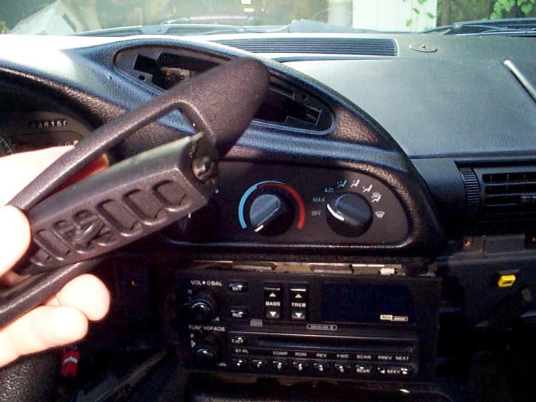
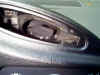
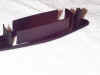
6. Now that you have the vent out, go ahead and remove
the swivel part from the vent assembly. You can do this just by pulling it apart a
little and pulling out. If you have trouble, you can use a small flat headed
screwdriver to push in on the pin that holds it in place.

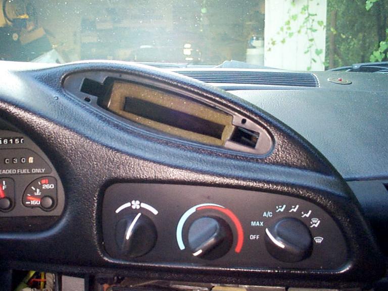
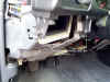
7. There is a piece of duct work that connects this
vent to the main system that now needs to be removed. You can see it in the picture
to the left. When you pull it out, it will look like the picture on the right.
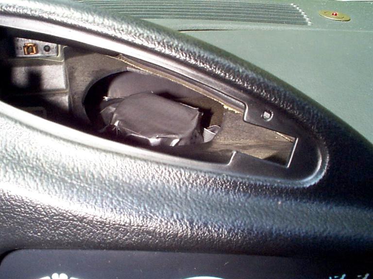
8. Now we can't just have air blowing around doing
nothing inside the dash, so we now need to block this hole. I was going to try
shoving a ball or something in there but didn't have anything the right size available so
I went the never fail route... duct tape! :) You can see what needs to be
blocked off in the picture to the left. The picture on the right shows my duct tape
work in action!
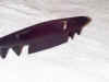
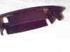
9. OK, now for the rough part :) You have to do
a little hack job on your air conditioning vent in order for the ScanMaster to fit.
If you screw it up, I don't think these cost too much :) I got mine right on the
first try though and I was just experimenting :)
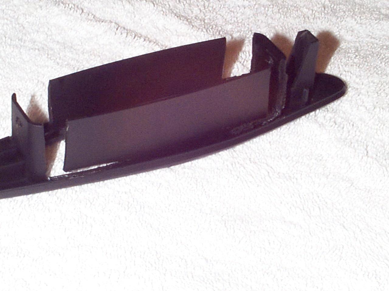
I hacked mine up with my Dremel using a cutting
wheel/sanding disc . Either of these will cut through the plastic like butter.
I recommend studying both the ScanMaster and the vent to get a good idea of what
you want to do before you turn on that Dremel. Also, a steady hand helps because you
are going to be getting very close to visible areas... one slip and you just bought
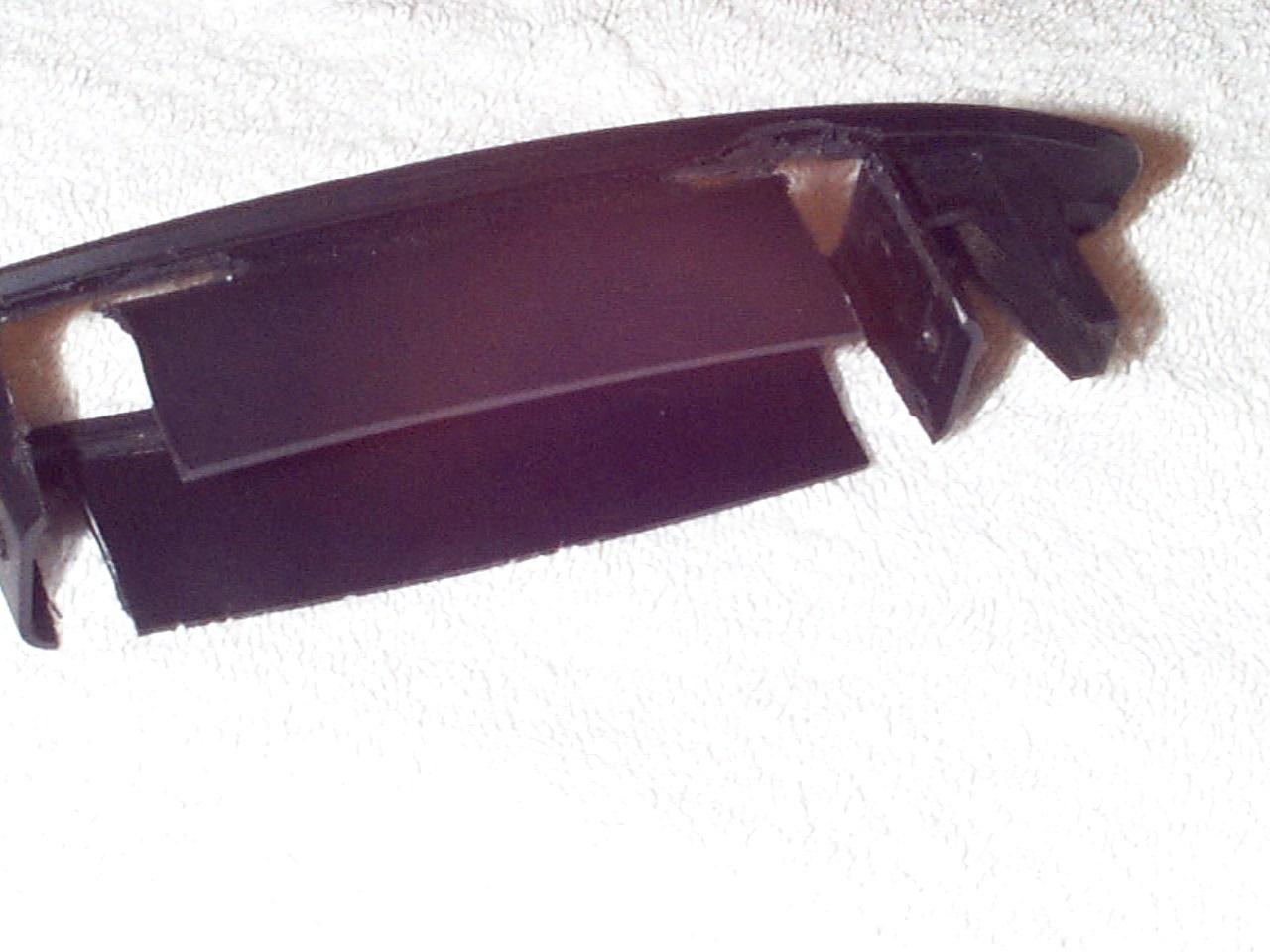
yourself a new vent :) Below are various angles of what the finished product should
look like. The idea is is to cut the plastic all the way to where the vent plastic
starts to turn textured. This will allow the ScanMaster to sit closer to the front
of the vent. The "flaps" that are created help to hold the ScanMaster in
place. Also, take a drill and drill a couple small holes in the side flaps.
This will allow you to connect wire or tie-wraps to hold the ScanMaster in place.
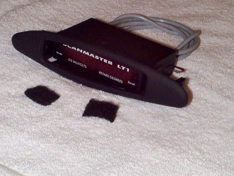
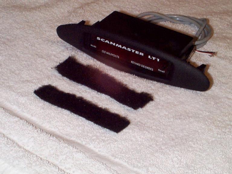
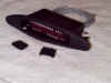
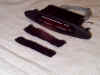
Since this vent wasn't actually designed to hold a
ScanMaster, it's not quite a *perfect* fit... although very close! Because it's not
a perfect fit, there is about 1/16" around the sides and top/bottom of the ScanMaster
when it is inserted into the vent. I was able to overcome this small problem with a
couple pieces of cheapo black carpeting (I got it from either Wal-Mart or AutoZone for $7
a while back). Just cut four pieces about the size of the four sides of the
ScanMaster in length. I folded the side pieces then used a knife to push them in
from the back. The top and bottom pieces I laid carpet side facing the ScanMaster
and used a butter knife again to push them in place. It ended up looking pretty
good! When looking at it from the front, you can just see the carpet on the sides
and only a very small portion of it. The carpet for the top and bottom I put there
more to prevent being able to see light from the back (since the windshield defroster
would allow light to come in from the back). Below are the pieces of carpet I cut.
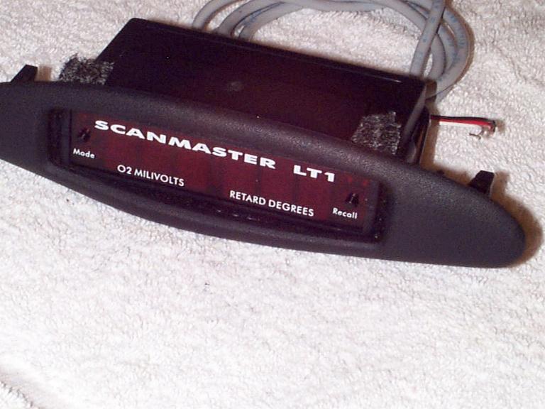
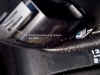
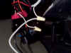
Now you have to secure the ScanMaster in the vent. I
did this by using small tie-wraps. I suppose you could use wire but I had tie-wraps
laying around so I used those :) Here is what the tie-wraps look like. It is
VERY snug in there and won't be going anywhere! The pic is a little bright but I did
that on purpose so you could easily see the tie-wraps.

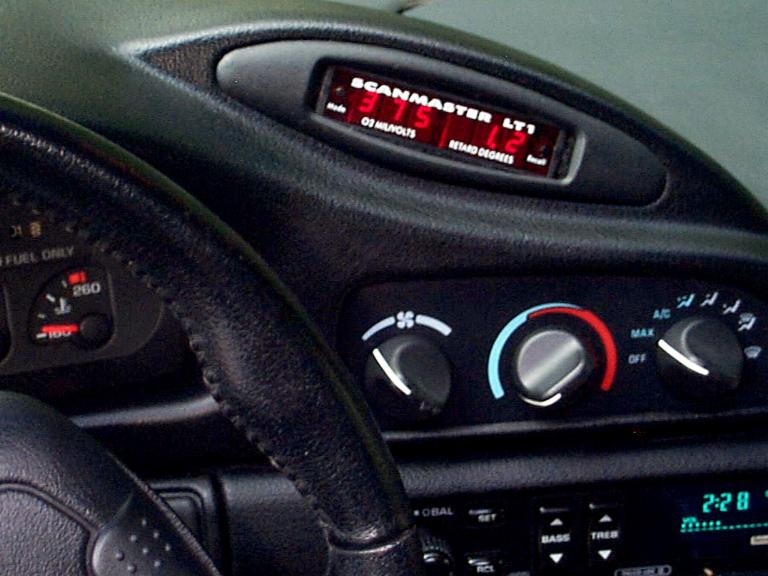
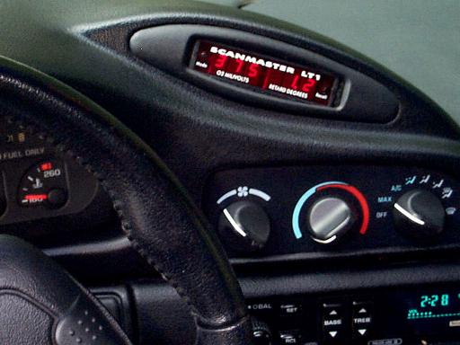
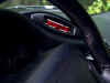
And now the finished product mounted in the vent!

The rough part is over! Now it's on to the fun part...
connecting it all up!
10. Do a little test fit just to make sure everything
is good before you snap everything back in place :)
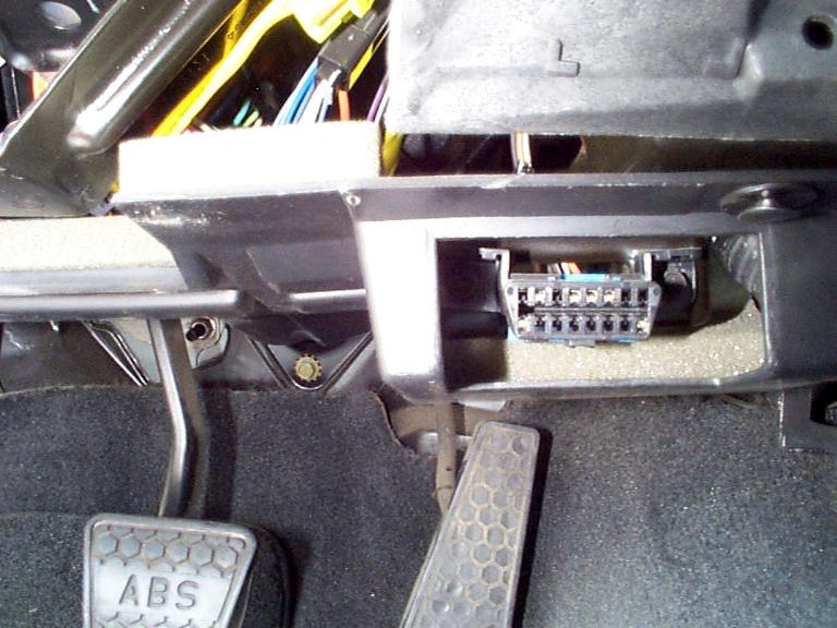
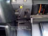
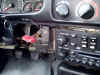
11. Now it's time to make the electrical connections.
I made mine at the ALDL port itself. Everything is there that is needed for
this device to work. For those that don't know, the ALDL is located just above your
right shin when you're sitting in the car. Here is a picture of it.
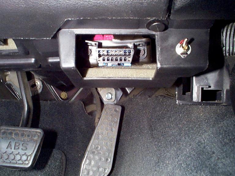
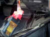
12. To make this a little easier, pull down the
plastic piece that goes around the ALDL connector. This is held up by a couple
ribbed plastic pins. Just pull down kinda hard and they will come out. Once
you've done this, unscrew the two 9/32" screws holding the ALDL port in place.
It will look something like this.
13. Now that you have easy access to the ALDL wires,
it's time to make the electrical connections! Go ahead and feed the ScanMaster
wires down from the top. You can easily see an area for them to go through to the
ALDL connector, but it might take a little fishin' to get them to go. Since I
also have a 94 Z28, I wanted to add a little flexibility with this install so I could swap
the ScanMaster between cars if I ever wanted to. So, I installed a couple connectors
about 8" or so from the ScanMaster itself. I got these from Radio Shack and
soldered the wires in place. Here's what it looks like... in case you have another
LT1 and want to do the same. This will allow me to easily unplug the ScanMaster.

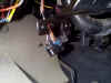
For the connection to the ALDL wires, I used red Scot-Lok (I
think that's the name of them :) connectors. They allow splicing into wires without
having to cut any wires. They make splicing very easy when working in a tight area
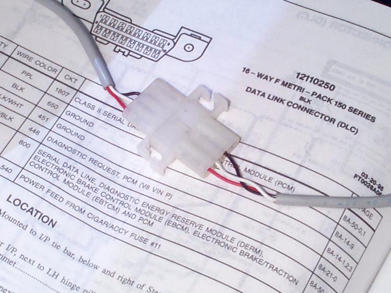
such as this! On my 96SS, the connection is as follows: The ScanMaster RED wire is the power wire and gets connected to the ORANGE wire on the ALDL connector in location #16. This is a
nothing more than a power feed from the cig lighter, fuse #11. The ScanMaster BLACK wire gets connected to the BLACK wire on the ALDL connector
in location #4. This is your ground wire. The ScanMaster WHITE wire (data
wire) gets connected to the TAN wire on the ALDL connector in
location #9. Keep in mind, these are locations for a 96 with an OBDII connector so
if you have a different year, yours may be different. Here is what the connections
look like when finished.

Go ahead and try her out! If it doesn't work, check
your connections as sometimes these splice connectors don't always work like they should.
Once you get your connections made and the unit working, go ahead and button this
up down here by reattaching the ALDL connector to the frame piece and reinstalling the
underside dash piece with the two push in ribbed plastic pins.
UPDATE: I have just found
out that the ScanMaster operation interferes with scan tools such as Diacom or possibly
even a GM tool that your dealer would use. I have Diacom and what happens is that
every 2 or 3 seconds both the Diacom and ScanMaster have a quick blip of erroneous data.
I'm currently trying to find a permanent fix for this but so far nothing. I
tried to install a diode in the ScanMaster data line but the ScanMaster wouldn't even turn
on with the diode in place. (Just found out the ScanMaster actually requests data
from the PCM! That's why the diode trick didn't work :)
A very easy fix for this problem (and a must do thing if you
take your car into the Chevy dealer or have Diacom) is to place a simple single-pole,
single-throw switch in the WHITE data wire of the ScanMaster. This will shut the
unit down when the switch is turned OFF. This will allow Diacom and the Chevy
dealer's monitoring equipment to function properly. I'll keep this paragraph up to
date with any info I find that might allow us to use both the ScanMaster and Diacom at the
same time. In the meantime, if you have any ideas or suggestions let me know!
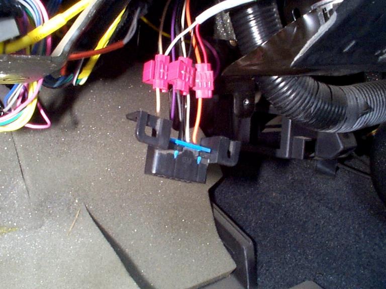
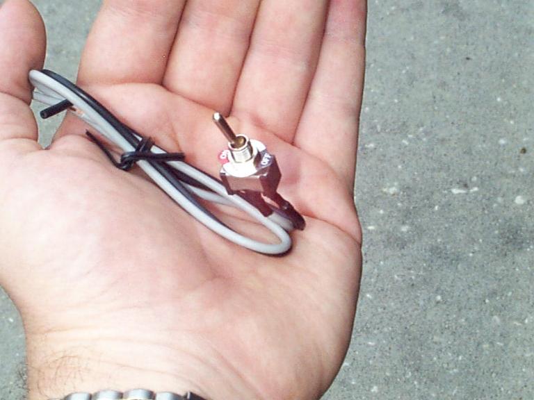
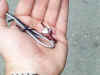
Now for the switch install. I actually had a
single-pole, single-throw switch in the garage so I just used that one :) A
single pole, single-throw switch has only two prongs on it. Here is a picture for
you non electrical types out there :)
Next you need to find a good place to mount the switch so
you can determine how much extra wire you will need. You can use standard speaker
wire if you want. My switch came with long enough wires already attached. Your
switch may not have any wires on it all and you'll have to add them yourself. I
chose to mount my switch down by the ALDL connector. It's a good location out of the
way yet easily accessible. Now that you know where you want to mount the switch, you
can make the connections. All you have to do is cut the WHITE wire coming from the
ScanMaster and splice in your switch as shown below. I don't normally use wire nuts
(normally use the plastic crimp caps) but since I installed the switch in the lower
plastic panel I wanted to have the ability to remove this panel in the future without
having to cut any wires. If you do use wire nuts, just check them and make sure they
are tight!
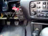
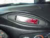
There you have it! Here is what the switch will look
like when you get everything put back in place.
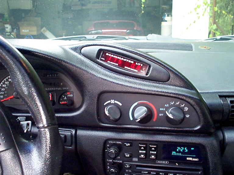
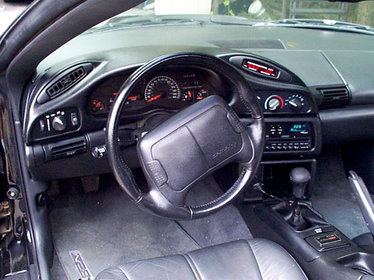
Now that you have everything working, push the vent with the
ScanMaster in place and reinstall all your trim pieces. It's now time to sit back
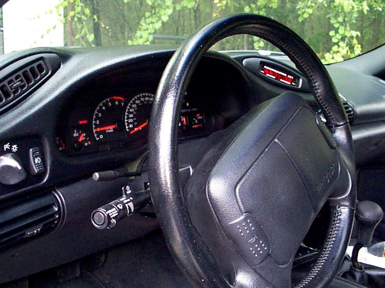
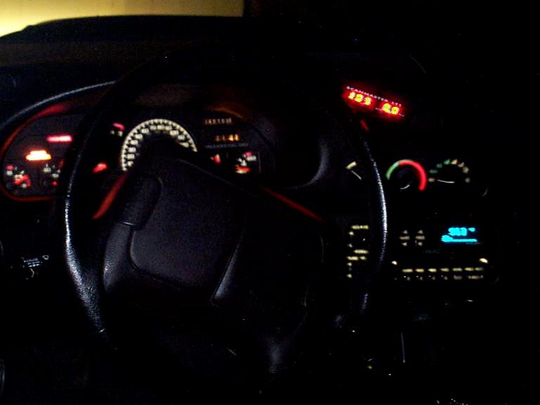
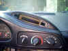
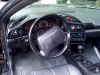
and admire your work because we're done! :-) Below are some pics I took right
after I finished. Notice how I have 1 to 2 degrees of knock retard while just
idling!?!? Hmmm???
It's a little blurry because I think the camera was
focused on the steering wheel :)


Well, that's it! I hope you enjoyed the page and maybe
even got a little use out of it :) I'm always happy to hear comments or suggestions.
Also, if you try this for your own ScanMaster installation, please let me know how
it went for you! bfranker@tampabay.rr.com
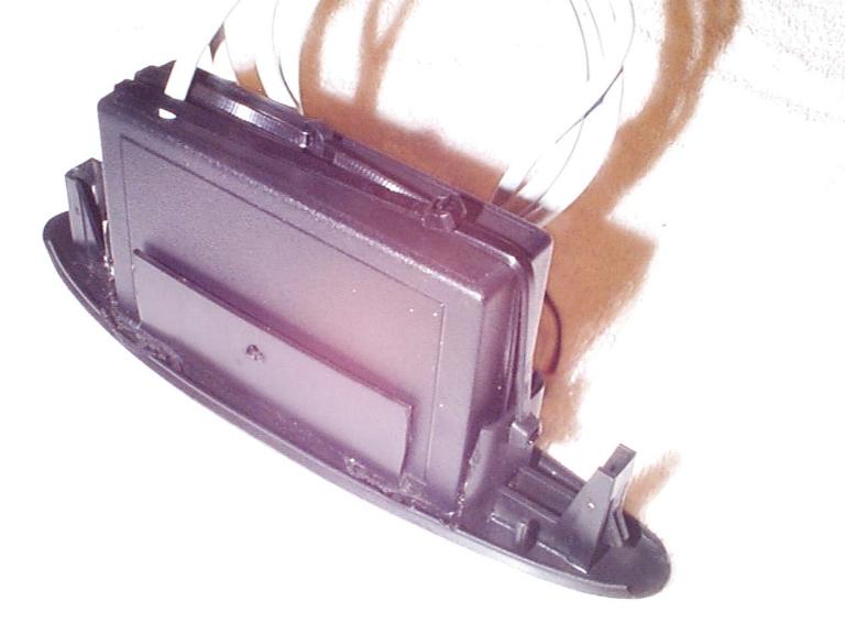
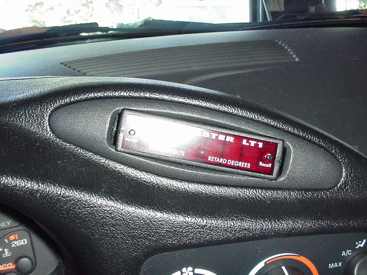
NOTE: For those of you that want to be able to remove
the ScanMaster for use in multiple cars, you'll need to cut the vent differently since the
above shows the ScanMaster being slid in from the back... unless you want to take out the
entire vent each time! If you think you may want to do this, below is a picture
(given to me by a person that used this page for his install!) that will give you an idea
of what it will look like. By cutting the vent in this manner, you should be able to
install and remove the ScanMaster from the front.
WOW! It's now been four or five hours since I
installed the ScanMaster and I just got back from a trip to town. After actual hands
on use, I am VERY impressed! This is even a neater and more useful gadget than I
originally thought! :) I am SO glad I mounted the ScanMaster where I did. This
location provides for extremely easy access (even while driving) to switch between the
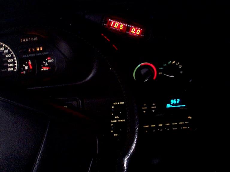
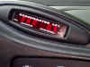
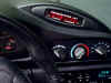
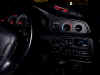
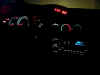
different modes of operation. Also, it looks VERY cool at night :) It looks so
good that I decided to take my photographic abilities to the limit :) My digital
camera has the ability to manually adjust the shutter speed... although I've never used
this feature until tonight. I thought I would try to let all you see what this unit
looks like mounted in this location at night. I don't have a tripod and I had the
shutter speed set to between 1 and 2 seconds so the pics are a bit blurry but not all that
bad considering I was holding the camera as still as I could! Well, here are the
night time pics!


|