I'll first start off by
describing a little about just what this kit does, the differences between the Full
Install and the Basic Install and also show you how this compares to a stock 93 to 96
Camaro Tail light.
Listed below are the different sections of
the tail light
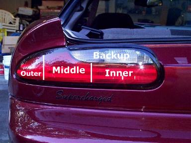
Below is the layout for a stock tail light
| Parking light |
Parking light
Brake light
Turn signal |
Backup light |
| Parking light |
Below is the layout you'll have if
you choose the Basic Install
(B) = Bright Filament (D) = Dim Filament
Turn signal 3rd
Brake 3rd |
Parking light (D)
Turn signal 2nd (B)
Brake 2nd (B) |
Backup light |
Parking light (D)
Turn Signal 1st (B)
Brake 1st (B) |
Below is the layout you'll have if
you choose the Full Install
(B) = Bulb Bright Filament (D) = Bulb Dim Filament
Parking light (D)
Turn signal 3rd (B)
Brake 3rd (B) |
Parking light (D)
Turn signal 2nd (B)
Brake 2nd (B) |
Backup light |
Parking light (D)
Turn Signal 1st (B)
Brake 1st (B) |
As you can tell from above, by doing
either the Full Install or Basic Install you'll end up (per side) with 3 sequenced brake
lights instead of just the 1 in the middle and 3 sequenced turn signal lights instead of
just the 1 middle. You can also see there isn't that much of a difference between
the Basic and Full Install... the difference being with the Basic install the outer
section isn't lit when the parking lights/head lights are on where as with the Full
Install it is. I opted for the Full Install because I wanted all three sections to
be on when the lights were on.

|
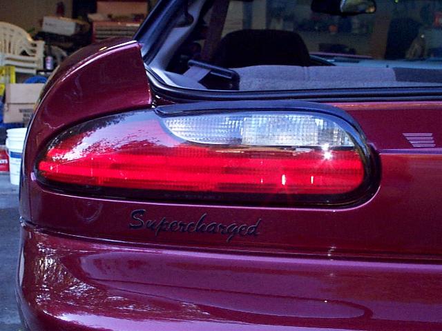
| These "blah" tail lights are about to go
away and be transformed into something a bit unique and quite the attention getter. When I started the install of these on my Camaro, I was a bit concerned
they may appear to be a bit "ricey" if you know what I mean. BUT, that is
FAR from the case. These add a very nice touch and are no where near a
"rice" mod IMO. |
 |
|
 |
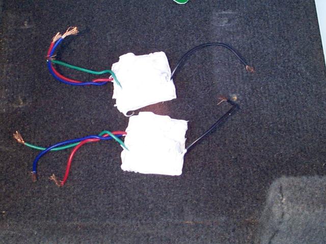
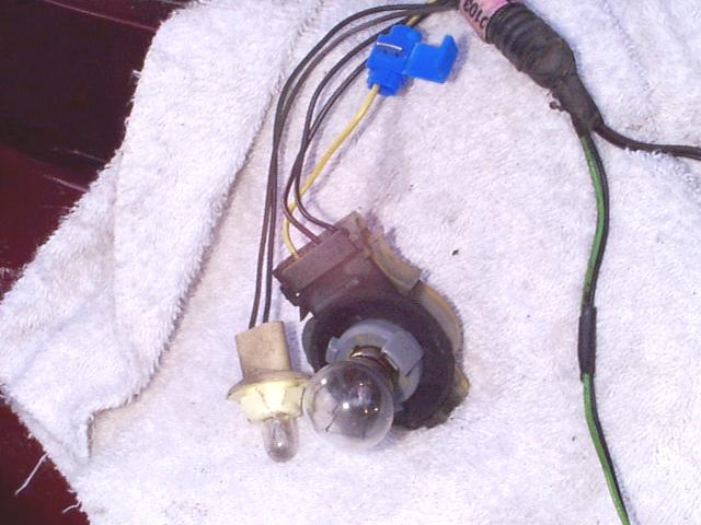
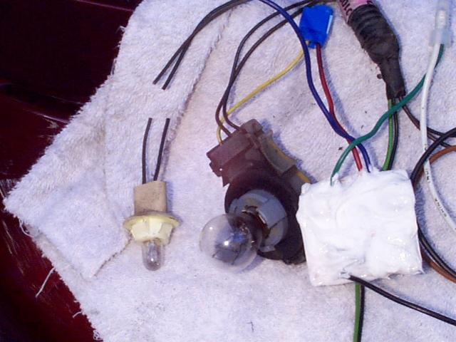
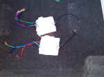
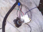
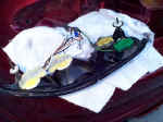
| NOTE: WebElectric's sequencers are
much more "professional" looking and come in a nice case. The pictures
here are of the sequencers I purchased from Damion several years ago. Included with the Basic Kit are:
- Two sequencer modules. These are the "brains" of
the operation and what control the sequencing.
- Two GM 90 degree double contact sockets.
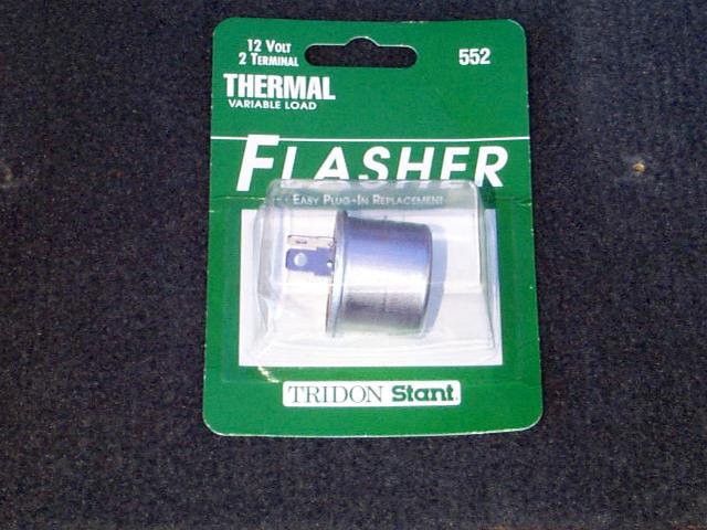
- One flasher. This flasher is actually a hazard flasher and
will provide a slightly slower flash rate which allows for all the lights to come on
during the sequencing.
In addition to what is included in the kit you will, at a minimum
need a sharp knife and electrical tape. This is at a bare minimum!!! I highly
recommend instead of a knife that you invest in a pair of wire strippers and cutters if
you don't already have some. Also, instead of electrical tape, I used blue Scotch
Lok connectors (pictured later) for making splices and plastic caps (butt end connectors
will work too) for connecting two wires. If using the Scotch Lok connectors you'll
need a pair of pliers to crimp them in place. Extreme people may whip out the soldering
gun and solder everything and then shrink wrap it but these are just tail lights so for me
the solder and shrink wrap are a bit excessive ;-) |

|
|
|
| I will detail here both the Basic and the Full
Install. The first method is the Basic Installation which is quick, easy, and can be
performed with basic hand tools. The second method is the Full Installation method.
See above for a description of description of the difference between the two install
methods. The Full Install is a bit more time consuming and requires modifying your
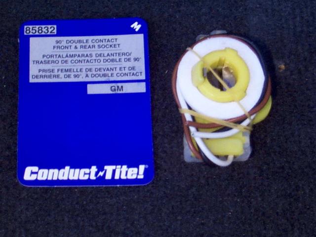
the tail light assembly and purchasing more parts for the install. If you didn't
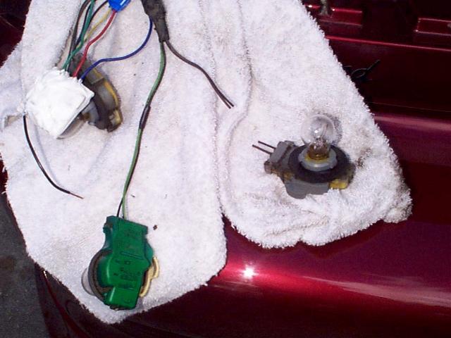
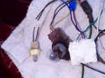
purchase the Full Install Kit from the get go but would now like to do this, it will
require two more of the GM sockets shown above and two 2057 bulbs. I bought the
sockets (model number 85832) at Auto Zone for $4.99 each and a package of two 2057 bulbs
for $1.79. If you don't have an Auto Zone near you the sockets may be a different
part number... that's ok, you're just looking for a GM 90 degree dual contact socket like
shown in the picture. You'll also need a Dremel and a cutting type drill bit. So, if
you bought the Basic Install Kit and now are deciding you want to do the Full Install,
it's going to cost you an additional $12 or so (assuming you already have a Dremel).
Damion only charges $12 more for the Full Install Kit plus he modifies the sockets
for you... not a bad deal at all :) |
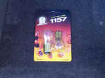
(Wrong bulbs pictured... need 2057!)Will
get new picture! LOL! |
|
|
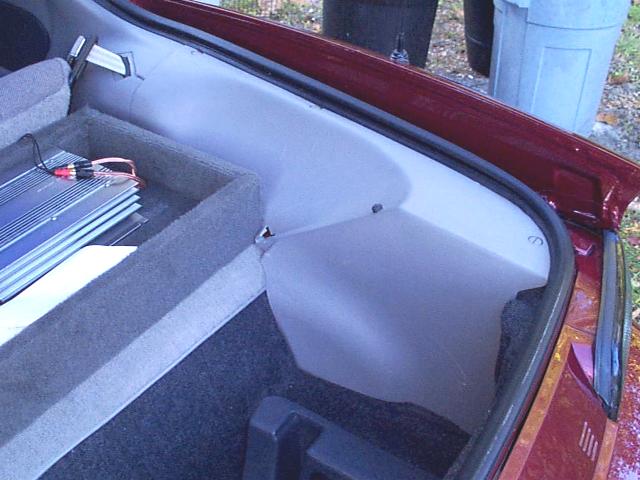
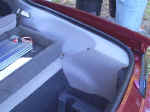
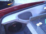
| We need to gain access to the back side of the tail
lights so we can remove them. To do this you will need to remove the two side panels
pictured here. You do not need to remove the back "carpet" piece as you
can just bend that out of the way as needed. The driver side
panel is removed by just pulling up on it. It is held in place by ribbed plastic
pins. After you get the driver side panel off you may notice the plastic ribbed pins
stayed in the metal holder portion of the car. If this is the case, just remove them
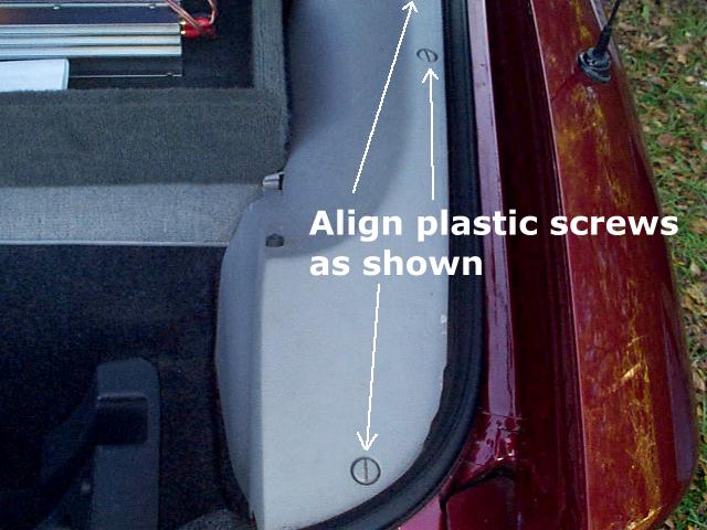
and place them back in the plastic panel. Your spare tire is stored under the
passenger side panel so its removal is a bit different. You need to align the three
screws as pictured (only two shown) and the panel will just lift off. |

|
|
|
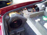
| With the two plastic panels removed you will now need
to remove your spare tire. You may not NEED to but it will sure make getting the
tail light out much easier :) In my case I also had to pull out my Stealth Box. |
|
|
|
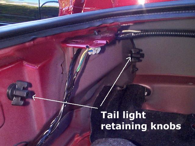
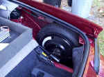
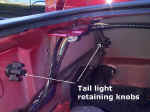
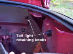
| With my spare tire and Stealth Box removed I now had
access to the plastic retaining knobs which hold the tail light in place. Just
unscrew the two plastic knobs on each side and you will then be able to remove the tail
lights. |
|
|
|
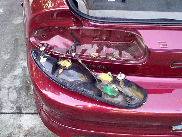
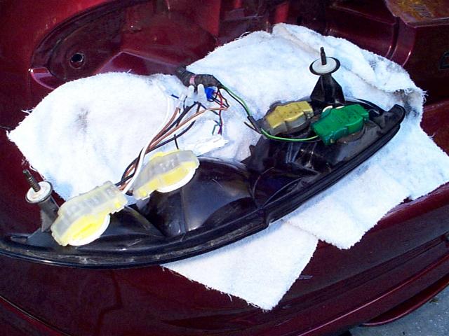
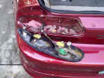
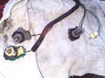
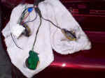
| With the retaining knobs removed you will be able to
just pull the tail light assembly straight out and rest it on the rear bumper cover.
I pulled the driver side out first then the passenger side. After I removed
the driver side I thought it would be a good idea to place a rag down so as to not scratch
my bumper cover :) Right after I took the picture I did place a rag on the bumper
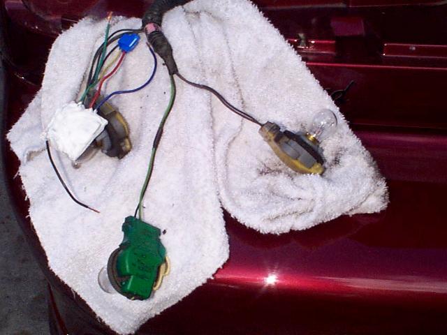
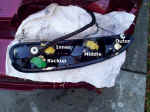
for the driver side :) For the install I'll refer to the
different lights as the inner, middle, and outer. I have them labeled in the bottom
picture here and you can also look near the top of this page for a description. The
backup light is easy to tell because it is the only socket which is green! |
|
|
|
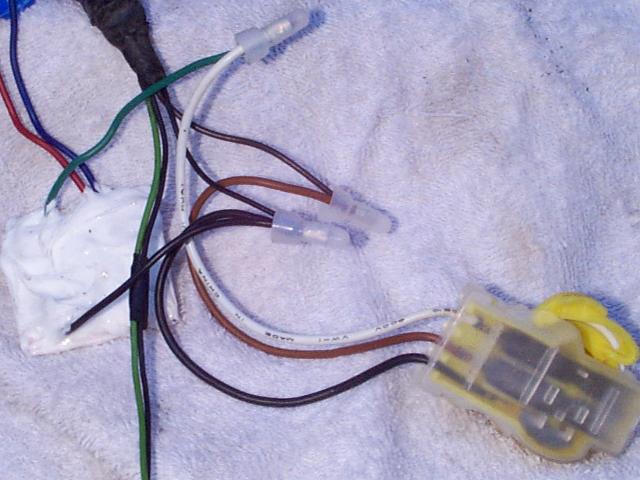
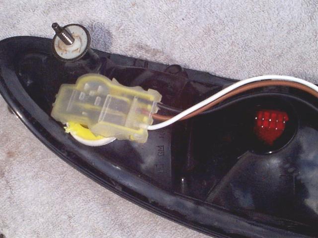
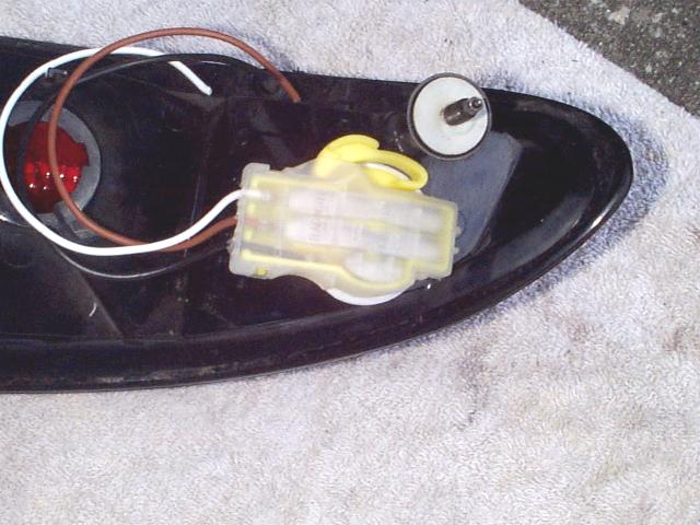
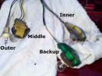
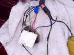
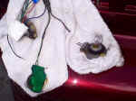
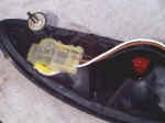
| The top picture here are the driver side light
sockets removed. The bottom picture are the passenger side sockets removed. The only difference between the two sides is on the MIDDLE socket.
The power wire on the driver side middle socket is YELLOW and
on the passenger side this same wire is GREEN. Other
than this difference the process for hooking the modules and sockets up will be the same
for both sides. Therefore, I'll often times only detail the install for one side. |
|
|
|
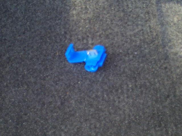
| The first thing we are going to do is work on the
middle socket. This socket will not need to be changed because it is the current
turn signal socket and already is the proper 3 wire socket. The
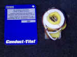
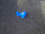
first picture is one of the Blue Scotch Lok connectors I mentioned earlier. These
work great for making splices as you don't need to cut the wire you are trying to splice
in to. If using the Scotch Lok connector cut the RED
wire on both sequencer modules as shown so there is no frayed wire showing. |
|
|
|
| On the driver side locate the YELLOW
wire on the middle socket and place the Scotch Lok connector over the yellow wire as
shown. If you are not using these connectors cut the YELLOW
wire a couple of inches up from the socket. |
 |
|
|
| On the driver side, slide the RED
wire of the sequencer into the Scotch Lok connector around YELLOW
wire and crimp it down with a pair of pliers. If you are not using the Scotch Lok
connector then twist together the two YELLOW wires and the RED sequencer wire (I'll assume you know that you need to strip
back a portion of the insulation on the wires ;). The idea is the same as with the
Scotch Lok connector... just more difficult :) Do the same
on the passenger side middle socket but instead of a YELLOW
wire you should have a GREEN wire. Make your
connections to this GREEN wire as shown in the bottom
picture.
This completes the work on the middle socket. |
|
|
|
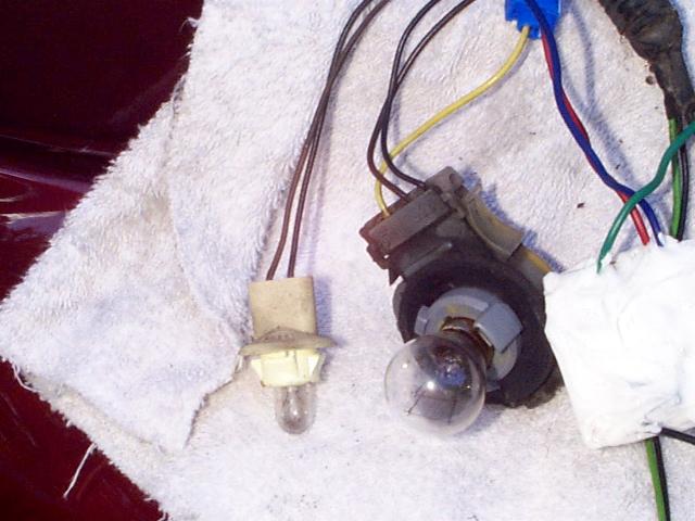
| Now we are going to work on the inner socket.
Notice your current inner socket looks about like the middle one we just worked on BUT
this inner socket has only two wires. That won't work with our sequencer so we need
to get rid of this socket. Cut both the BLACK and BROWN wires of the socket as shown here and put this socket aside.
Repeat this on the passenger side. |
|
|
|
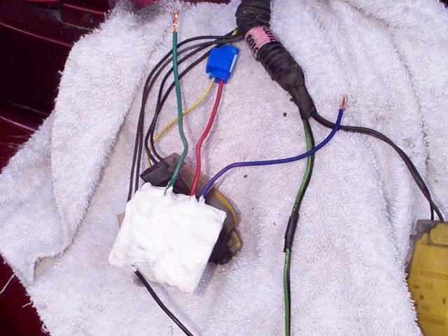
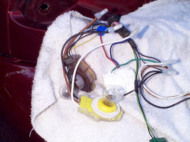
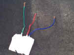
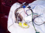
| Now you are going to use the sockets supplied with
your kit. Grab one of these sockets. It has three wires... a BLACK, WHITE, and
BROWN. Connect the socket's BROWN
wire to the BROWN wire that was for the socket we just cut
off. Connect the socket's WHITE wire to the GREEN wire
of the sequencer module. Connect the socket's BLACK wire to the BLACK wire for the
socket we just cut off and also the BLACK wire from the sequencer module. It'll look
similar to the picture here. Remember, if you aren't using caps like I am then
you'll need to tape up your connections with electrical tape. Take the bulb out of
the socket you just cut off and insert it into your newly installed socket. NOTE:
When placing a bulb in these new sockets it's not a bad idea to also put some
"bulb grease" in there. It is a grease that prevents corrosion. You
may notice this grease in the factory sockets. You can purchase this grease in a
packet at your auto parts store for about $1 :) It's not 100% necessary but a good
idea! Repeat this for the passenger side.
This completes the inner socket. All that is left now is the
outer socket! |
 |
|
|
| If you are doing only the Basic Installation continue
reading on how to wire up the outer light. If you are doing the Full Installation,
skip to the next set of instructions. I didn't do the Basic
Installation so don't have many pictures but it isn't difficult.
On the outer socket (the smaller one) slide a Scotch Lok connector
over the BROWN wire. If you are not using these
connectors, cut the BROWN wire about 2 inches up from the
socket. Do not cut the black wire!
Insert the BLUE wire from the
sequencer module into the Scotch Lok connector on the BROWN
wire and crimp it in place. If not using these connectors then twist together your
two BROWN wires and the BLUE
sequencer wire to make the splice.
Repeat this on the passenger side.
For the Basic Installation you are about done and can now skip
down to the section where you'll connect the sockets into the light assembly. |
BASIC
INSTALLATION
ONLY
|
|
|
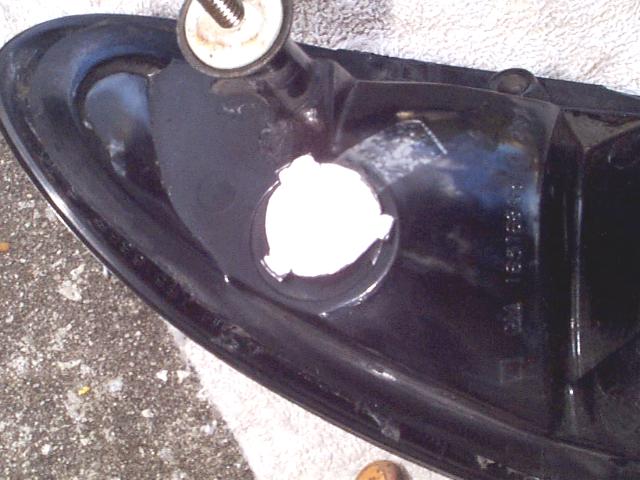
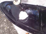
| Full Installation Only:
Locate the small outer socket and cut it off as shown in the lower picture.
We will be replacing this socket with one of the new 85832 GM sockets you purchased from
the auto parts store or got in the Full Install Kit. As
stated above in the pricing section, doing a Full Install places a dual filament bulb very
close to the actual tail lamp red housing. I'm not saying this will happen but
rather there is a possibility your tail light could get a very small dimple in it due to
the heat from this dual filament bulb. Just be aware of this and make sure you
modify the hole in the housing so the bulb is as far away from possible from the edge of
the housing. |
|
|
|
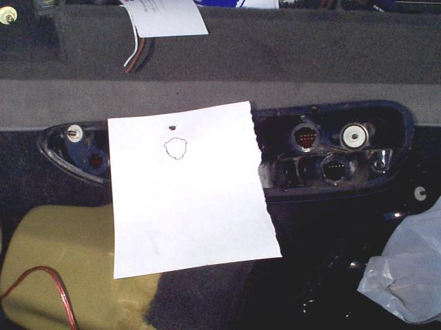
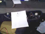
| Full Installation Only:
Ok... now is where the fun begins :) We need to be able to install the new GM
socket in the area where the small socket currently resides. As you can see, it
obviously won't fit as is and the hole will need to be modified. I decided to rather
than just "wing it" to make a template. I took a sheet of ink-jet paper
and pushed it over a tab near the middle socket hole. I then held the light assembly
up to a light source (the sun!) and traced the opening. You cut this out and there
is your template! |
 |
|
|
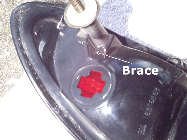
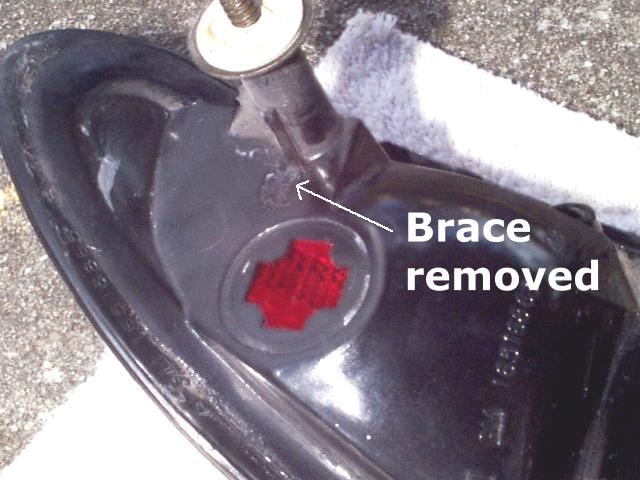
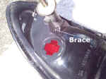
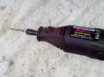
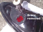
| Full Installation Only:
The first thing you'll notice is there is a plastic brace which is slightly in the
way. You can see this in the first picture. For all
the "hacking" I did on my tail light assembly I used a cutting type drill bit
like shown here. It looks like a standard drill bit but it's not... it is made for
cutting plastic just like we need to do here.
The bottom picture shows the brace removed. |
|
|
|
| Full Installation Only:
With the brace removed take your template and tape it in place. Now this is
VERY important. This is basically NO room for error here because it is a very tight
fit. Because of this you need to place your template NOT directly over the current
hole but rather as far down and to the inside as you can. If you don't do this your
socket will hit the metal part of your car and your tail light assembly will not go all
the way in. In the picture you can see where my template is not centered on the
hole. When taping on your template you need to take into consideration that once the
socket is inserted into the hole it is TWISTED to lock in place. You need to take
into account this "twist" when aligning your template. This will take some
thinking and eyeballing on your part so take your time here and double check what you plan
to do. Once the template is in place, trace around it with a Sharpie marker or
something you can see. No use your Dremel and cut the hole to the proper size.
Another very important note here is that you can always make the hole bigger... you
can't easily make the hole smaller again!!! So, whatever you do, error on the size
of SMALL. Cut out a little less than you think you need to then test fit with the
socket. If it is too big, GOOD, because all you'll need to do is place the socket
over the hole and see where you need to remove more plastic. If it just falls in
then you screwed up and may need to purchase a new tail lamp assembly and you don't want
to do that so cut small!!! Take note that on the driver side socket I ended up
removing the "tab" on the side with my Dremel. You can see it
"missing" in the picture to the right. If you purchased the Full Install
kit your sockets should already come modified for you. The
last two pictures show mine complete with the new sockets in place. Once you get
yours in place and holding tight like mine here you will need to test fit them. When
you are test fitting them you will see what I meant by there is very little room here to
mess up. You may need to slightly rotate the socket one way or the other but that
shouldn't hurt so long as it stays tight in place. If you happened to mess up to the
point that no matter how you rotate your socket you can't get the tail light to test fit
properly because the socket is hitting the car, there may be hope :) You can modify
the socket and hack away at the plastic with your Dremel to reduce its size. If you
need to you can take the clear plastic cover entirely off and fill the area with silicone
caulk. |
|
|
|
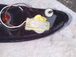
| Full Installation Only:
With the hard part out of the way all that is left is to connect the socket. Connect the socket's BROWN wire to the BROWN wire that was for the socket you just cut off. Connect
the socket's WHITE wire to the BLUE wire of the sequencer
module. Connect the socket's BLACK wire to the BLACK wire for the socket you just
cut off. It'll look similar to the picture here.
All electrical connections are now complete! |
 |
|
|
| With all electrical connections made it is now time
to put the assembly back together. Note,
the sockets will be arranged differently than they were before! If
you notice this, you aren't confused... it's supposed to be like this :)
The socket which has the RED
sequencer module wire connects to the inner socket hole.
The socket which has the GREEN
sequencer module wire connects to the middle socket hole.
The socket which has the BLUE
sequencer module wire connects to the outer socket hole.
The backup light socket goes back into the same hole and when
finished all sockets should look like this picture. |
 |
|
|
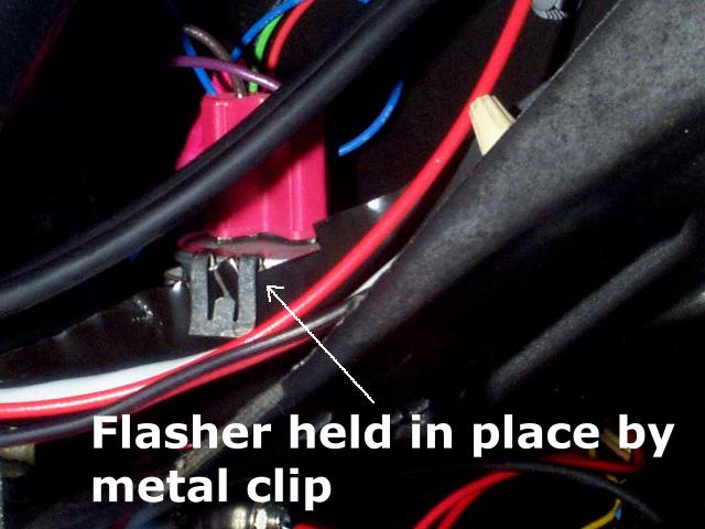
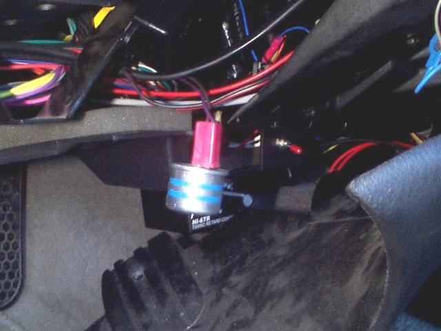
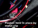
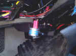
| Now you can change out the flasher. You'll need
to remove the panel under the steering wheel. Once this panel is removed the flasher
is located to the bottom right. The easiest way to find the flasher is to turn on
the ignition and turn on your turn signal then follow the clicking noise. Be careful
here because there are two flashers. One of the signals and one for the hazards...
you don't want to replace your hazard flasher! Once found, turn the ignition back
off, remove the flasher and install the new flasher which was supplied in the kit. |
|
|
|
| Check out your connections! Turn on
your hazards and check your lights to be sure they all light up in sequence. Have
someone press the brake and make sure the brake lights work and initially light up in
sequence. Turn your car on and check the signaling to the left and then to the
right. If one or more bulbs do not light up, double-check the connections to that
bulb. Also check the power and ground connections going to the sequencer
module. You'll also want to check to make sure your bulb didn't just burn out.
That happened to me... for some reason my inner driver side light didn't work, I checked
all connections and all seemed fine. I finally decided to change the bulb and it was
the bulb... whoops :) Enjoy your new sequencer lights and
all the comments you'll get from them! |
|
|
|
|