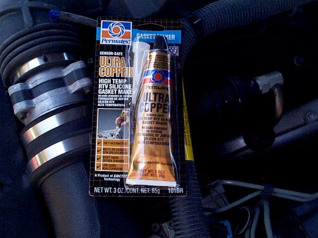
| You'll need some high temperature RTV sealant.
I had heard good things about the Permatex Ultra Copper so that's what I used.
Haven't had any problems since the fix was performed. |
|
|

|
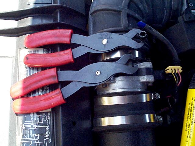
| You'll also need a couple fuel line removal
tools. |
 |
|
|
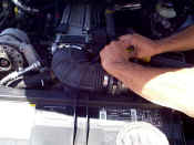
| The throttle body and fuel rails will stay on
the intake. The rubber bellows needs to come off though. There are several
connections that will need to be disconnected. We did this a while ago and my memory
isn't as good as it used to be... can't remember everything so if I don't mention
something and it is obvious it needs to come off, go ahead and remove it :) |
 |
|
|
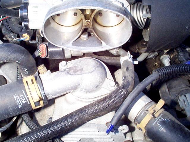
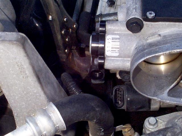
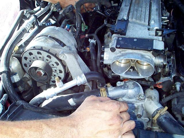
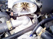
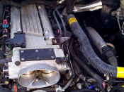
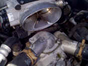
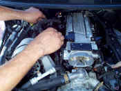
| During this intake oil leak
fix, we also performed the throttle body bypass mod since these lines needed to come off
anyway. This picture shows the line going into the throttle body. With the
95, no shunt is needed to perform this mod. You can simply take this hose off and
move it to the metal line which the throttle body outlet hose connects to... this will
bypass the throttle body. Very easy :) |
 |
|
|
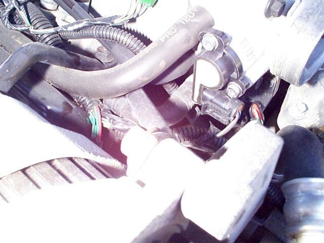
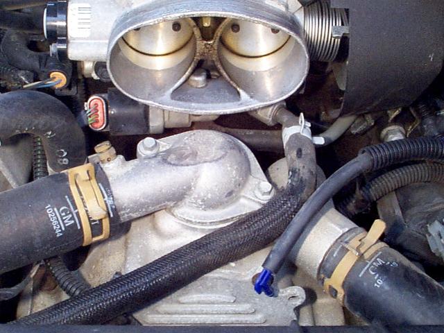
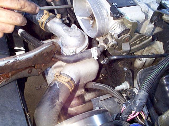
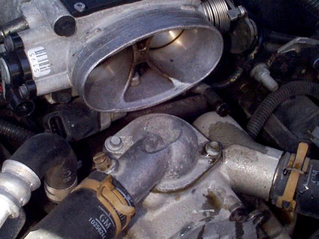
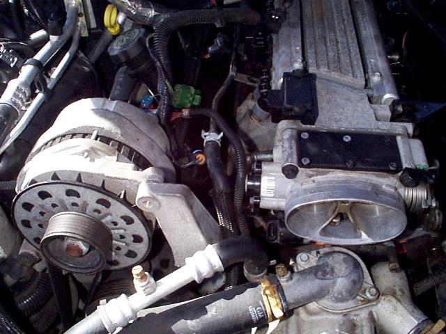
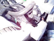
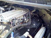
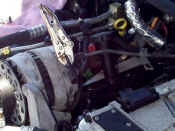
| Here you can see the
"L" shaped rubber coolant hose coming out of the throttle body and connecting
into a metal line. The metal line is difficult to see but you'll be able to see it
better in some later pictures. The line I'm talking about has a clamp on it and is
just below and behind the TPS. |
 |
|
|
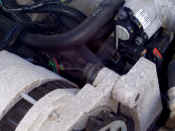
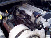
| Another picture of the above
but a little darker. |
 |
|
|
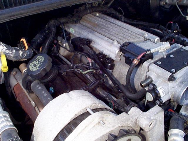
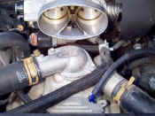
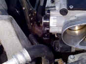
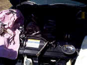
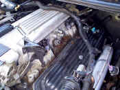
| Front pic of throttle body area. |
 |
|
|
| Throttle and cruise cable plastic shield
removed. |
 |
|
|
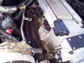
| Disconnecting some vacuum lines and hoses.
The fuel injector connections are also disconnected... keep these straight as to
which one goes where. They are pretty well laid out in order coming out of the
harness so this is difficult to mess up. Also notice the supply and return fuel
lines have been disconnected as well. Remove your gas cap to bleed a little pressure
off the tank but still expect these to possibly be pressurized. You'll probably
spill some gas but not much... just make sure you don't have super hot headers/manifolds
at this point or an open flame :) |
 |
|
|
| Closer pic of the fuel line connections to the
fuel rail. |
 |
|
|
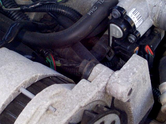
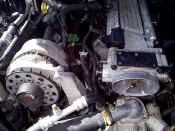
| A few more hoses removed as well as the
alternator bracket and bolt that fastens to the intake. |
 |
|
|
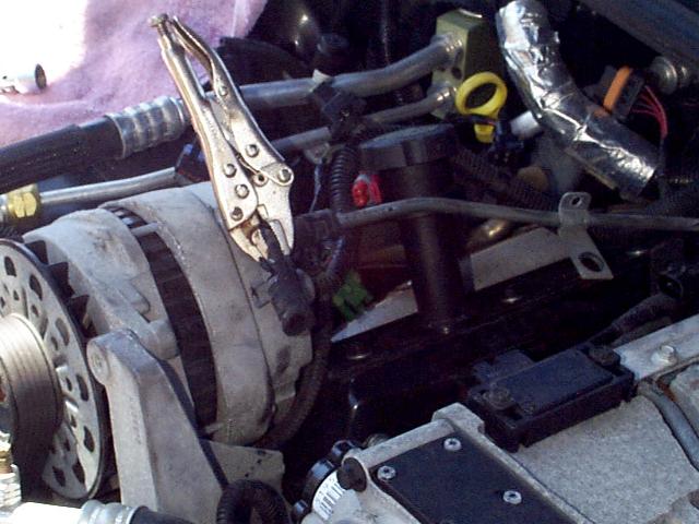
| IAC and TPS connectors disconnected. Also, note the vice grips pinching the rubber line for the coolant coming
out of the throttle body. This was done as a precaution but even after the vice
grips were removed, not much coolant came out. |
 |
|
|
| Inlet hose pinched off and
working on prying off the outlet coolant hose. Remove inlet hose as well. |
 |
|
|
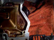
| This is the outlet coolant
line removed. Notice the metal line I talked about above. This metal line is
the one where we'll later connect the rubber hose which was removed in the picture
immediately above this one. |
 |
|
|
| Inlet coolant hose removed
with only a minor amount of coolant spilled. Getting close to pulling the intake :) |
 |
|
|
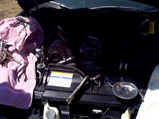
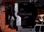
| Just a pic of the work area. |
 |
|
|
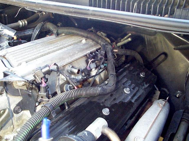
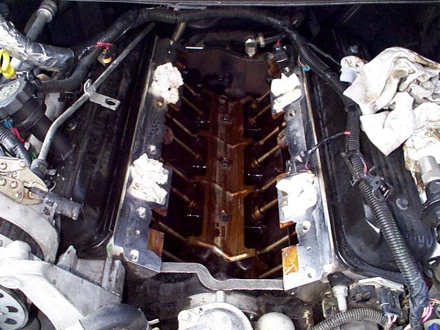
| Intake bolts removed and most connections now
off. Try to clean this area as good as you can to prevent debris from falling into
the engine when the intake is pulled. Don't forget to disconnect the EGR line...
can't see it here as it's on the back side of the intake. Another
good shot of the metal coolant line. |
 |
|
|
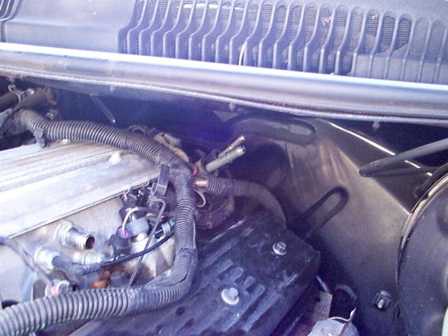
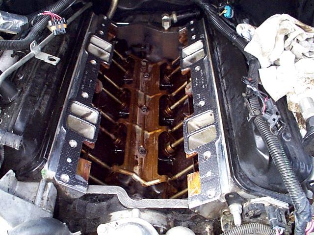
| Intake bolts removed on driver side.
Most lines and harnesses are now out of the way to pull the intake. |
 |
|
|
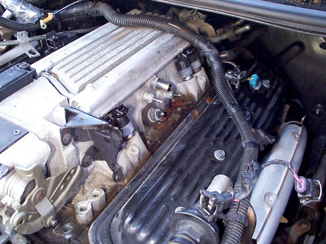
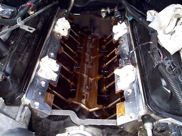
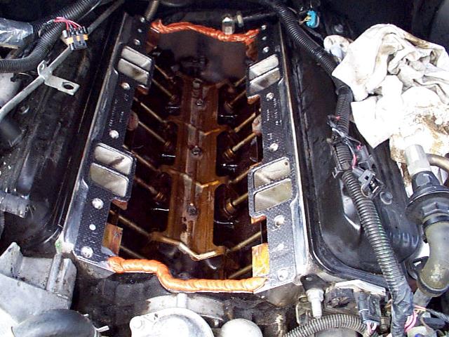
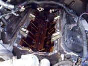
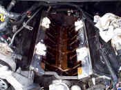
| This is what mine looked like right after the
intake was pulled. Notice the EGR line in the back. |
 |
|
|
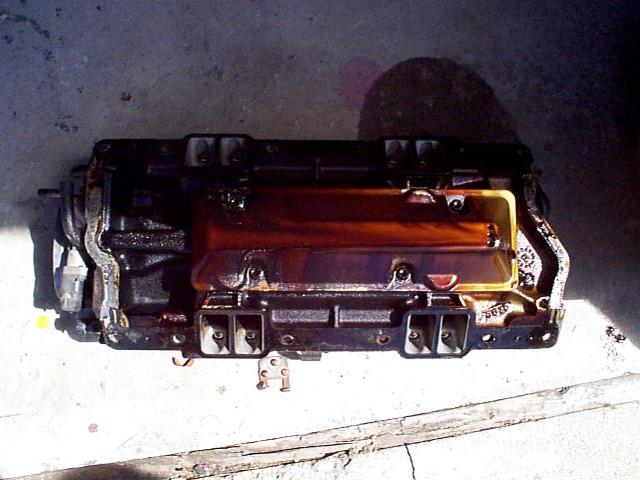
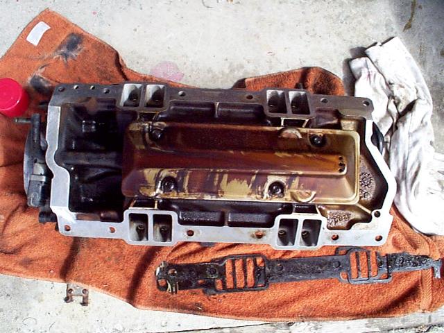
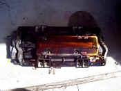
| Picture of the bottom side of the intake
manifold. |
 |
|
|
| Clean up the intake with some rags and
carb/brake cleaner. Also, take some sandpaper and rough up the edges of the intake
where the RTV sealant will be making contact. This will help to ensure a good seal. |
 |
|
|
| Other side scratched up for good seal. |
 |
|
|
| Put some rags in the air intake on the heads
and clean the areas where the gaskets will go. Also, clean and rough up with
sandpaper the areas here where the RTV sealant will be placed. It is also a good idea to
stick some rags in the lifter valley if you think you might get some "junk" in
there. I didn't and didn't have much trouble but it doesn't hurt if you have extra
rags! |
 |
|
|
| Cleaned up and about ready to go. You
may need to use a razor blade to remove some of the old gasket material. |
 |
|
|
| The intake cleaned up and ready to go. |
 |
|
|
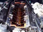
| Gaskets in place. If I remember right,
these are Felpro gaskets. |
 |
|
|
| RTV bead on front and back side. Do NOT get
stingy with the RTV. Put a nice bead on there... you don't want to do this again do you?
:) Place the intake back on. |
 |
|
|
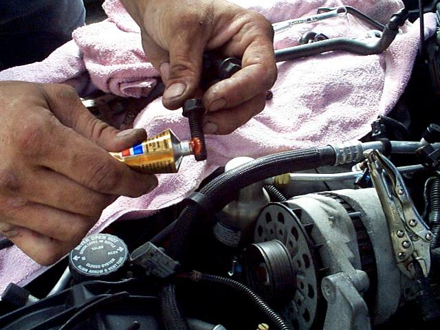
| When putting the bolts back in, we also put a
little sealant on these. I don't have any torque specs because we just snugged them
up :) After doing a number of these projects, you get a good feel for how tight
things need to be and when torque specs are and are not important. I'm not saying
this is a good practice, but in this instance, we didn't use a torque wrench :) I
recommend you do, however, because it is a good practice and the correct setting is 35
ft-lbs. |
 |
|
|
| Here you can see the inlet
coolant line connected to the metal line which runs along side the intake. The
throttle body bypass mod is now complete. |
 |
|
|
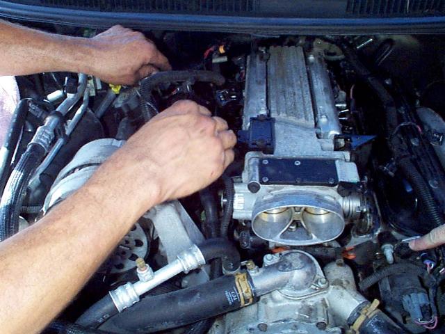
| Buttoning things back up. |
 |
|
|
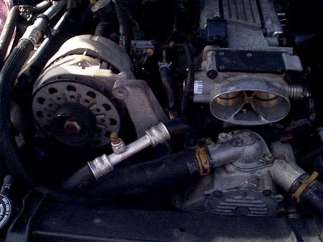
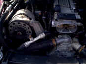
| Here is a better shot of the
new routing for the throttle body coolant line and it connecting into the metal
line. It has not been bolted down in place yet. |
 |
|
|
| And here is an even better
shot :) Now all that is left is to hook up
all those connections you took off. I didn't take notes here because I knew there were
already a few different very detailed intake leak fix it pages out there. Using
those detailed instructions with these pics makes for an easy afternoon project and some
saved money! Remember, if at all possible, do NOT start the car for about 24 hours
to allow the RTV sealant to setup properly. |
 |
|
|
|
|
|
|
|
|
|
|
|
|
|
|
|
|
|
|
|
|
|
|
|
|
|
|
|
|
|
|
|
|
|
|
|
|
|
|
|
|
|
|
|
|
|
|
|
|
|
|
|
|
|
|
|
|